Salas - actually with the current limiter and the rather large cap in the amp, the problem is largely solved. I wouldn't mind having the reference voltage turn on slowly - as in the circuit you link to. But I don't see a way of doing that. With zeners, one could add a large cap across them, but that's a no-go with a 0A3.
But, actually, I'm pretty happy with the performance of the circuit as is. If it works as well on the bench as it does in the simulator, I'd be quite happy.
~Tom
But, actually, I'm pretty happy with the performance of the circuit as is. If it works as well on the bench as it does in the simulator, I'd be quite happy.
~Tom
Folks,
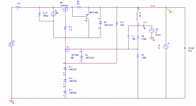
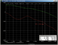
Here's where I'm landing. This regulator actually shows remarkable performance. I'll follow up with graphs later. Ignore L1, C2, V5. They are for the AC loop analysis.
The three zeners D1~D3 will be replaced by a 0A3. Powering the reference from the output side of the regulator resulted in an improvement of over 25 dB in line regulation. It should start up fine as the CCS supplies 1 mA through Q5, thereby, pulling the gate of the pass device high. This in turn charges the load cap and powers the reference.
Worst case phase margin is about 60 degrees (high input voltage, no load). Under load with typical input voltage, the PM is about 90 degrees.
Using a CCS as a drain load on the error amp device boost the gain by some 20~25 dB. More importantly, it ensures consistent performance across input power supply variation.
The unity gain bandwidth is over 20 kHz. /me like...
~Tom
Attachments
Plots
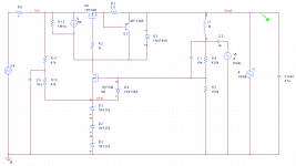
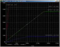
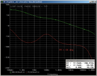
I went back to feeding the reference from the input voltage as connecting it to the output voltage seemed to create LF instability.
The latest schematic and plots are attached. Salas: It looks like 25-ish dB of loop gain at 1 kHz.
~Tom
I went back to feeding the reference from the input voltage as connecting it to the output voltage seemed to create LF instability.
The latest schematic and plots are attached. Salas: It looks like 25-ish dB of loop gain at 1 kHz.
~Tom
Attachments
Last edited:
Tom, I noticed you haven't split R15 and put a decoup cap in......try inserting that on simulation program...you will get a vast improvement on that poor -50dB ripple rejection. By doing this and relating the benefits to component layout, at this low ripple level one has to be careful with the neg layout that it won't take much to pick up the odd mV ripple from input rectifier-cap rectifier returns.
As a cap is fitted on the output, this indicates an undesirable pole in the Bodeplot response...so naturally reducing it will increase the noise.
The circuit I submitted appears overprotected but I live in quite a electrically noisy environment with alot of summer storms.
I get alot of queries regarding a high current low dropout 6.3V. There seems to be a shortage of suitable packaged devices so I've opened another thread on this with a discrete circuit to give others more ideas.
richy
Tom, I noticed you haven't split R15 and put a decoup cap in......try inserting that on simulation program...
R15 is actually a model of the output impedance of the current source. I the actual circuit I'll use one of the IXYS CCS parts. I slapped 1 Mohm in there as that's probably in the right ballpark.
By doing this and relating the benefits to component layout, at this low ripple level one has to be careful with the neg layout that it won't take much to pick up the odd mV ripple from input rectifier-cap rectifier returns.
Yep. It doesn't take much of a layout screw-up to ruin -55 dB of anything.
As a cap is fitted on the output, this indicates an undesirable pole in the Bodeplot response...so naturally reducing it will increase the noise.
Unfortunately, that cap is required in the amp I'm driving with this supply. I could change the amp topology or change the cap size, but I don't feel like doing that. The amp performs well and the cap has been optimized for the best frequency response. Makes the power supply design a [FEMALE DOG]. Tough...
")
I get alot of queries regarding a high current low dropout 6.3V. There seems to be a shortage of suitable packaged devices so I've opened another thread on this with a discrete circuit to give others more ideas.
The main challenge I have with low-voltage, high current regulators is how to deal with dissipating the heat in a graceful way.
I've taken the route of not generating the heat in the first place. I use switching regulators... With solid performance too. If you're into switchers, check out National's SimpleSwitcher lineup. LMZ12003, LMZ14203 come to mind. LM2734 or LM3102 also.
I can justify dissipating 15~20 W for the amp supply, but for the heaters I go a different route.
~Tom
Good stuff Switching regulators.....right up my street.
Yup. LMZ12002 set to 5.0 V out for a 300B. Rockin...! More info here:
http://www.diyaudio.com/forums/tubes-valves/175695-300b-switchmode-filament-supply.html#post2338290
Note the data update here:
http://www.diyaudio.com/forums/tube...switchmode-filament-supply-2.html#post2340389 (post #17)
I see no reason to go with linear supplies for the filaments. Other than maybe nostalgia. But no real engineering reason.
~Tom
Hello all,
I built a Maida regulator which regulates at 500V. I have the same problem that it will not regulate without a load. However, when a small load is connected, it regulates no problem so I am not worried. A have attached a schematic and load regulation graph containing experimental values. The regulator is to supply 500V to KT88's in PP ultra linear. I wanted current limiting, so I made came up with a little circuit on the output of the regulator to limit the output current to around 400mA. It seems to work ok.
I would like some advice on any improvements I could make to this regulator. I also want the regulator to have a soft start, and reach 500V about 20 seconds after turn on. Is there any way to do this using an RC network given my schematic?
Thanks
Attachments
Deso: Q1 is indeed reversed. You could also make R1 somewhat larger- as drawn, you're running 50 mA though it, which seems excessive, depending on the hfe of Q1 (you might use a Darlington or MOSFET there). You can current limit without throwing away the low output impedance of the reg by placing the Q2/Q3 circuit before the reg. The 1u output cap can be problematic in terms of stability and certainly compromises noise performance (though that's not a big deal for an output stage). I would recommend a 30-50u aluminum electrolytic in series with a small (3-5R) resistor.
Yes, soft start is possible, but it may take more than an RC to make it bulletproof. There are easier ways of skinning that cat, assuming there's even a cat there to be skinned.
Yes, soft start is possible, but it may take more than an RC to make it bulletproof. There are easier ways of skinning that cat, assuming there's even a cat there to be skinned.
As an aside, has anyone built a Maida Vale using a TL783?
What's the motivation? The reg has the zener minus Vbe drop across it.
I would like some advice on any improvements I could make to this regulator. I also want the regulator to have a soft start, and reach 500V about 20 seconds after turn on. Is there any way to do this using an RC network given my schematic?
Thanks
Problem with a soft-start on the HV Maida (if you use the circuit on the nat semi datasheet) is that you're only going to "soft-start" the voltage regulated by the LM317, i.e. limited by the zener D2.
The external transistors on a MAIDA need to be decently heat-sinked.
Sy: Since Q1 has a really low DC gain (approx 20), I am worried about starving the zener when the regulator draws around 0.4A. I agree though I could use a higher value. I could also use a darlington but I couldn't find any that where rated for 600V or higher. From what I have read in this thread many people use low voltage transistors or darlingtons for Q1. If I were to use a transistor with a rating below 500V would the regulator still be reliable? Even at startup?
I will move the current limiting circuit at the input of the LM317 and add more capacitance on the output with a small series resistor. I did notice that there was significant ac ripple (0.2Vrms) when the regulator was loaded to 0.4A. The 1uF cap could be the reason for this.
As far as a soft start goes, I am not sure how to do this when using such a high voltage. I might just forget about it and hope the tubes hold out. I am using solid state rectification so I wanted the HT voltage to be delayed.
Don't skimp on pass transistor voltage rating!
Hfe of 20 is indeed very low. You can make it a darlington pretty easily with a second transistor. TO220 units with 800V ratings are under a dollar. Or use a MOSFET- the slightly higher output impedance isn't too important here since it's followed by a regulator.
Hfe of 20 is indeed very low. You can make it a darlington pretty easily with a second transistor. TO220 units with 800V ratings are under a dollar. Or use a MOSFET- the slightly higher output impedance isn't too important here since it's followed by a regulator.
The 1u output cap can be problematic in terms of stability and certainly compromises noise performance (though that's not a big deal for an output stage). I would recommend a 30-50u aluminum electrolytic in series with a small (3-5R) resistor.
Maida's circuit was published with an output network of 1uF MKT and 2.7 Ohm series resistor - and for good reasons.
For a regulator with a 400mA current limit, increasing the capacitor to 50uF will mean a turn-ON cap charging pulse of 40+ ms at current limit. In terms of Safe Operating Area, the pulse will be almost half that time at 300V+ across the transistor, and 400mA - deeply into the second-breakdown zone of a BJT. Even moving to MOS, a husky 140W, 800V power FET like the FQP5N80 (which has no second-breakdown) will need to be at a very low temperature to survive that pulse. This is pretty much what was happening to Tom at the start of the thread - Dead Darlingtons!
In any case, higher C values do not improve the dynamics of the regulator as a study of National data will reveal. With 3+ ohms of series resistance in the output network (increased further by ESR of electrolytics at 500V durability), the output impedance is dominated by the 317's loop well above the audio spectrum, and by the frequency range where the capacitor gets useful, a 1uF would do just as well. Not to mention the improved stability and parasitics of a 1u film cap, easy availability of 630V parts, and dramatically reduced lifetime problems.
Another reason, hinted at in Maida's note, for the choice of output network components, is transient performance. Regardless of the series resistor (at practical values), increasing the output capacitor risks havoc with the phase response - the 317's internal frequency compensation is completely undermined by the additional pass transistors and resistors in the Maida architecture, and the response to the kind of load changes felt by a push-pull amplifier will only be reasonable for modest capacitances. Omitting the series resistor is likely to turn the regulator into a full or part-time oscillator!
There may be a small reduction in LF noise with 50uF, but in practice, if low noise is important, the Maida is not a good solution, compared to the kind of discrete circuit that Tom is pursuing.
Best advice is to stick to the 1uF MKT + 2.7 ohms specified by Maida, or better still, take the path to discrete component regulation, like Tom's design.
What's the motivation?
The motivation is I have plenty of TL783.
Cheers
Ian
For a regulator with a 400mA current limit, increasing the capacitor to 50uF will mean a turn-ON cap charging pulse of 40+ ms at current limit. In terms of Safe Operating Area, the pulse will be almost half that time at 300V+ across the transistor, and 400mA - deeply into the second-breakdown zone of a BJT.
Experimentally, the several dozen Maida-type regs I've built with the 4R/47u output network (not to mention the regs in the several dozen Red Light Districts and ImPasses built by others) haven't gotten the memo. They survive turn on and are dead nuts stable. Could you show your sim?
- Status
- This old topic is closed. If you want to reopen this topic, contact a moderator using the "Report Post" button.
- Home
- Amplifiers
- Power Supplies
- High Voltage Regulators (Maida or zener)