If you can get a GZ37, these will drop at least 20V more than a GZ34. Watch out for extra heater current though!
A better way is to configure the PS to quasi- choke input. Remove the electrolytics at C1 [cap after rectifier] and replace with MKP [stacked] polypropylene. Panasonic box type for preference. Use PSUDii to find the value of the MKP: 1uF to 5uF are good starting points.
Cheap motor run MKPs sound horrible IME. Stacked MKP are cheap and 630V rated, and sound fine.
A better way is to configure the PS to quasi- choke input. Remove the electrolytics at C1 [cap after rectifier] and replace with MKP [stacked] polypropylene. Panasonic box type for preference. Use PSUDii to find the value of the MKP: 1uF to 5uF are good starting points.
Hi Rod
Yes, I have been reading up and this might be the way to do it. Pity I don´t know how to use the PSUDII or I would have.....
Thanks
Try using a buck winding on the primary- a 12.6V filament transformer will work. That will be the most efficient way to do it rather than burn up heat in a higher rectifier drop or series resistors. It will also drop the heater voltages, but not by much- if you drop 30V out of 520, your 5V heater will drop to about 4.7V. That could work in your favor as well.
What's your Load Current?
Rod
I have 390VAC, 0,5A, 18 OHM
Cheers
It work work fine.
You can make 33uF or so by using 100uF/400V electrolytic (Panasonic HA or HB or TSUP, Nichicon KX). Use three in series like you have two in series now, with 220K 1W resitor across each one, to keep the voltage balanced in each one.
Or you could use a quality MKP of 30uF/630V. I use and enjoy the AMPOHM [LCR] MKP series
AMPOHM WOUND PRODUCTS|FP-CA-10-AU|CAPACITOR, AUDIO, 10UF, 630VDC | Farnell United Kingdom
It work work fine.
You can make 33uF or so by using 100uF/400V electrolytic (Panasonic HA or HB or TSUP, Nichicon KX). Use three in series like you have two in series now, with 220K 1W resitor across each one, to keep the voltage balanced in each one.
Or you could use a quality MKP of 30uF/630V. I use and enjoy the AMPOHM [LCR] MKP series
AMPOHM WOUND PRODUCTS|FP-CA-10-AU|CAPACITOR, AUDIO, 10UF, 630VDC | Farnell United Kingdom
Rod
Oh shoot, I thought I had 30uf but checking now they are 50uf/600V. So I guess these won´t work?
An externally hosted image should be here but it was not working when we last tested it.
I was thinking of something like this. 1st cap 50uf/600V and then a resistor.
An externally hosted image should be here but it was not working when we last tested it.
Cheers
Last edited:
That would be a lot less capacitance.
THe other thing to check is that the output valves are correctly adjusted.
Presumably the original designer intended less than 500V on C2, and if the output valves are drawing less than the right current, the voltage will rise. Adjusting for more current, provinding you keep within rated dissipation on the anodes, might just pull it in.
If you lower the first pair of 47uf caps off rectifier you will be "closer" to a Choke Input Filter (.9* tranny secondary voltage) rather than a Cap Input Filter (1.4* tranny secondary voltage).
You can also model it in PSU designer.
EDIT - whoops, someone already recommended reduce caps size - the choke input deal... looks like I should read more, type less...
You can also model it in PSU designer.
EDIT - whoops, someone already recommended reduce caps size - the choke input deal... looks like I should read more, type less...
Last edited:
That would be a lot less capacitance.
THe other thing to check is that the output valves are correctly adjusted.
Presumably the original designer intended less than 500V on C2, and if the output valves are drawing less than the right current, the voltage will rise. Adjusting for more current, provinding you keep within rated dissipation on the anodes, might just pull it in.
Rod
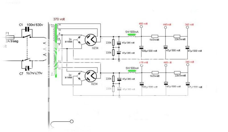
The PS was SS in the beginning but it was changed to tube rectified. C2 had 480V which is pushing it a bit but still under maximum load.
So what would you say about connecting the 50uf/600V cap after the rectifier and then a resistor, would this bring the voltage down?
Cheers
Might work for class A SE amps.
If you're running 100mA class A, 220 Ohms would drop 22V - but burn 2.2W (use a 10W part, wirewound, and mount well away from anything that can't stand the 200 to 300 degrees C of wirewound Rs). The amp may be degraded by the instantaneous volt drops, a little.
For PP class AB amps, the drops caused while the music plays would degrade the sound notably, I suspect, and the power burn in the resistor may be much higher, with music, depending on what kind of power valves you have in there.
O, it's Triode Dick's Bill. Adding a series resistor is certainly the wrong thing there.
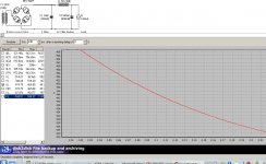
Here's a supply based on 10uF MKP. The voltage will be a tiny bit higher with your hybrid bridge - maybe 5-8V. This is a stepped load, corresponding to the standard KT88 conditions of 120mA idle, 300mA full power, 20ms later. the sag is slightly less with 25uF - the price for changing things.
IF the current at idle is different, these results will be off, so beware, and measure first.
Attachments
O, it's Triode Dick's Bill. Adding a series resistor is certainly the wrong thing there.
Here's a supply based on 10uF MKP. The voltage will be a tiny bit higher with your hybrid bridge - maybe 5-8V. This is a stepped load, corresponding to the standard KT88 conditions of 120mA idle, 300mA full power, 20ms later. the sag is slightly less with 25uF - the price for changing things.
IF the current at idle is different, these results will be off, so beware, and measure first.
Sorry Rod...you lost me there
What does this mean? Im not a techie, just a guy who likes to put things together. However Im learning, all thanks to you.
Cheers
But - I still think it is worth knowing what the current in each KT88 cathode is, before proceeding.
If the KT88s are tired out (and taking LOW current), the voltage will be higher than expected. Fixing this before modifying the supply is a better way ahead.
I would expect 55 to 65mA at 500V, as a start, unless Triode Dick has a different spec.
If the KT88s are tired out (and taking LOW current), the voltage will be higher than expected. Fixing this before modifying the supply is a better way ahead.
I would expect 55 to 65mA at 500V, as a start, unless Triode Dick has a different spec.
But - I still think it is worth knowing what the current in each KT88 cathode is, before proceeding.
If the KT88s are tired out (and taking LOW current), the voltage will be higher than expected. Fixing this before modifying the supply is a better way ahead.
I would expect 55 to 65mA at 500V, as a start, unless Triode Dick has a different spec.
Ok, thanks Rod
I have brand new KT88´s in and biased at 60mA. So I guess I will try 10uf/630V caps instead if the ones Im using now.
Thanks again
- Status
- This old topic is closed. If you want to reopen this topic, contact a moderator using the "Report Post" button.
- Home
- Amplifiers
- Tubes / Valves
- Lowering B+ in PS