Pity I don´t know how to use the PSUDII or I would have.....Thanks
Time to learn. It's about the easiest design program there is (and I hate wasting my time learning the arcane habits of these type of programs).
It's accurate if you enter your transformer properties - and those here can help with that the first time.
I always check my designs for no-load voltages, i.e., output tube fails. That's the potential voltage your caps will see. And it's often quite a bit higher than the fully loaded voltage. Rate accordingly.
Sheldon
Can the PS be changed so that it is not a bridge? Can the joined HV leads on the secondary (6 & 9 ?) be treated as a CT? If the result is too low it could go back to the original diode-only approach, just not bridged.
Crazy talk?
If the secondary leads are not connected internally, yes you can use them as a center tap, but the voltage will be roughly halved.
Sheldon
Time to learn. It's about the easiest design program there is (and I hate wasting my time learning the arcane habits of these type of programs).
It's accurate if you enter your transformer properties - and those here can help with that the first time.
I always check my designs for no-load voltages, i.e., output tube fails. That's the potential voltage your caps will see. And it's often quite a bit higher than the fully loaded voltage. Rate accordingly.
Sheldon
Hello Sheldon
Well I guess it´s easy for you but I spent a couple of hours today and I didn´t get squat from it other than error messages saying things I dont know anything about. I have tried the PSUDII before with the same result. Im not new to computers or programs, the thing is my lack of knowledge in electronics, thats the problem. I don´t understand what values I have to feed into the program so it turnes out like crap. Anyway, I will give the PSUDII some more time later to try and figure it out but at the moment Im in need of some help from you guys.
Take care and thanks...
Measure the resistance of your primary, and your secondary. Then measure the unloaded voltage ratio. The safest way to do this, is to connect the secondary to the line voltage, and measure the voltage at the primary. That will give you the ratio (you can do it the other way, but then you will be measuring a multiple of the line voltage). From that ratio, you can calculate the unloaded secondary voltage (ratio times line voltage).
Now open PSUDII. Put the mouse over the transformer so that only the transformer is highlighted. Right click on the transformer and click edit. You will get a dialog box called Edit transformer properties. Click on the source resistance button. Enter your supply voltage (line voltage), primary winding resistance, secondary off load voltage (voltage derived above), and secondary winding resistance. Click OK. Now you've got your transformer values entered.
Leave the diode bridge for now in the sample schematic. We'll get back to that later. First highlight the resistor section (highlight box over the whole section, not just resistor). Insert an LC section. Highlight the resistor section again, and insert an RC section. Repeat for a second RC section. Now highlight the final resistor only (small highlight box over only the resistor). Change this to a Current source. Now highlight the preceeding RC section and insert a current source. Do the same for the first RC section. You should now have a transformer, diode bridge, cap, LC section, current source, RC section, current source, RC section, current source.
Now edit each component to match your circuit values. You will have to model the first series cap as a single cap of half the value. Forget the bleeders for now. This will give you the values for a ss diode bridge.
You can then change the SS diode bridge to a tube bridge. Your actual value will be halfway between them.
Sheldon
Thanks Sheldon
How do I get the bridged resistors on the first cap´s in the PSUDII?
Cheers
Thanks Sheldon
How do I get the bridged resistors on the first cap´s in the PSUDII?
Cheers
You can't. You have to model the first cap as a single cap, as I said in the previous post. Forget the resistors, you can't model them in this program, and you don't need to. (If you really want you can insert a current tap before the inductor, with the current calculated based on the expected voltage and your resistance. Either way, it won't make much difference.)
Sheldon
Use 5R4 rectifiers. They have about 40v more drop than what you are using and have only 2A heaters.
Hmmmm. this could be a solution. Thanks
BTW are you measuring the unloaded power supply, or with the complete amp?
Sheldon
im measuring loaded.....
Cheers
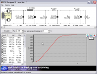
Here's a screen grab from PSUD. I don't know the inductor resistance, so just a guess there. I put in 370V at a rated 150mA for the transformer (it would be double that for your actual transformer, because you are running two channels.) I set it up as a full wave rectifier, to reflect the impedence of the rectifier. It will be slightly different for a bridge, but it will get you close. Voltage is taken at the first Current tap.
Attachments
If you have Morgan Jones Valve amps 4th ed, page 360 HT rectifier..shows a 317 job, I don't like using this chip or elevated B+ but the idea of configurating a HV power mosfet for 2nd post regulation (as cap multiplier)to drop the excess may be an idea. Obviously SS gate protection has to be engineered into any arrangement.
There are SS methods of regulating the neg return, but that creates more complications and may not be justifyable.
richy
There are SS methods of regulating the neg return, but that creates more complications and may not be justifyable.
richy
Hi all
Great news! I have succeeded lowering the B+. I changed the 2 first 47uf/500V caps to 2 10uf/630V Polys. Now I have 465V/445V/335V so im smack on what I wanted. Listening to the amp now and it sounds great. I hope I finally can put the building part of this project behind me now and start to enjoy the amp for music.
Thank you all for your input and help and I promise I will be back with more tricky questions for my next project.
Cheers
Here's a screen grab from PSUD. I don't know the inductor resistance, so just a guess there. I put in 370V at a rated 150mA for the transformer (it would be double that for your actual transformer, because you are running two channels.) I set it up as a full wave rectifier, to reflect the impedence of the rectifier. It will be slightly different for a bridge, but it will get you close. Voltage is taken at the first Current tap.
Thanks Sheldon, you where right and your PSUD simulations where spot on, se my latest post.
Take care......
I bet it sounds improved, too, if you found some good quality MKPs to put in there, in place of those Electrolytics.
Yes I believe it does. Im thinkung that I maybe will change the double 47uf cap for a pair of 47uf Polys. Tricky thing is what to do with the 500uf.....
Anyway, I will give myself a rest for the time beeing.
Cheers
Tricky thing is what to do with the 500uf.....
Might I suggest PSUD?
")
- Status
- This old topic is closed. If you want to reopen this topic, contact a moderator using the "Report Post" button.
- Home
- Amplifiers
- Tubes / Valves
- Lowering B+ in PS