Some time ago I posted a spreadsheet for generating the parameters for a transformer SPICE model. I have received some recent emails asking questions about it, and I have also seen the recent post from pweaudiotech with his spreadsheets. This has jogged my memory and made me remember that I made a much improved version over a year ago.
It generates the SPICE model as well a just the parameters.
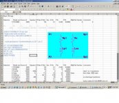
It will generate models for single ended, push pull, ultralinear, with or without multiple speaker taps.
Use is simple, instructions are included on the first sheet of the spreadsheet.
Attached is a screen shot showing the simplest case, a SE transformer with a single output. The xls file (zipped) is also attached.
The usual caveats apply :
This is a model, reality will be slightly different.
It does not model core effects ie saturation etc.
The parameters I have listed for various transformers may or may not be accurate, I have taken them from data sheets, from websites, from wherever, and in some cases where information was not available, just guessed. So put whatever numbers you think best in here.
Also, in some cases I have added multiple speaker taps to transformers that dont really have them, just to play around with them.
It generates the SPICE model as well a just the parameters.
It will generate models for single ended, push pull, ultralinear, with or without multiple speaker taps.
Use is simple, instructions are included on the first sheet of the spreadsheet.
Attached is a screen shot showing the simplest case, a SE transformer with a single output. The xls file (zipped) is also attached.
The usual caveats apply :
This is a model, reality will be slightly different.
It does not model core effects ie saturation etc.
The parameters I have listed for various transformers may or may not be accurate, I have taken them from data sheets, from websites, from wherever, and in some cases where information was not available, just guessed. So put whatever numbers you think best in here.
Also, in some cases I have added multiple speaker taps to transformers that dont really have them, just to play around with them.
Attachments

Thanks a lot!
Thank you very much for this interesting and helpful model.
Best regards,
Jose Angel Jimenez
Thank you very much for this interesting and helpful model.
Best regards,
Jose Angel Jimenez
sorry to sound foolish but how does one create the model in LTSpice?
Transformer Models
How do I build a transformer model?
The best way would be to draft a model with coupled inductors
with a mutual inductance statement placed as a SPICE directive
on the schematic. See the section on mutual Inductance for more
information. Inductors participating in a mutual inductance
will be drawn with a phasing dot.
The following example demonstrates a transformer with 1:3 turns
ratio (one to nine inductance ratio) with a sine wave input and
simulates for 0.1ms. The K is set to 1 to model a transformer
with no leakage inductance.
see page 185 of the manual: http://ltspice.linear.com/software/scad3.pdf
Attachments


sorry i understand how to define simple transformers as you have just posted but i meant how do i create the model to use with one of the transformers from robert maclean's spreadsheet. specifically how do i name the resistors 'Rp1' & inductors 'Ls1' etc to match the model text. i tried putting the value of the resistor as 'Rp1" but i get a "Can't find definition of model "RP1"" message.
Why don't you just add a normal R in series with L and give it the value calculated from spreadsheet
or right-klick on L and fill in the calculated value of R as <Series Resistance>
or right-klick on L and fill in the calculated value of R as <Series Resistance>
sorry i understand how to define simple transformers as you have just posted but i meant how do i create the model to use with one of the transformers from robert maclean's spreadsheet. specifically how do i name the resistors 'Rp1' & inductors 'Ls1' etc to match the model text. i tried putting the value of the resistor as 'Rp1" but i get a "Can't find definition of model "RP1"" message.
I havent tried yet, but isn't it just to copy the blue text in the worksheet into a 'spice directive' and stick that into the schem?
hmmm...I just tried and I also have trouble getting it to work. I drew up an exact replica of the transformer schem, and inserted the spice directive, and get 'Rp1: Missing resistance value.'
Of course I could type all values in manually, but that kinda makes the spreadsheet useless doesn't it?
Of course I could type all values in manually, but that kinda makes the spreadsheet useless doesn't it?
sorry i understand how to define simple transformers as you have just posted but i meant how do i create the model to use with one of the transformers from robert maclean's spreadsheet. specifically how do i name the resistors 'Rp1' & inductors 'Ls1' etc to match the model text. i tried putting the value of the resistor as 'Rp1" but i get a "Can't find definition of model "RP1"" message.
In LTSpice, you could use {Rp1} for the resistor's value and then have a .param spice directive to define Rp1, like .param Rp1=27.
There is a very good paper about modeling transformers, at :
http://www.onsemi.com/pub_link/Collateral/AN1679-D.PDF
Based on that paper, I made a spice model for a two-winding transformer for which you only need to insert simple measurements, and spice calculates the model parameters. It can be downloaded from here:
Spice Component and Circuit Modeling and Simulation
I thought the subckt we got from the spreadsheet did just that. Why else create it? Sorry, I'm really dumb when it comes to computer language. Thanks for link, I'll look into that...tomorrow if time permits.
SemperFi
You are correct about how the spreadsheet is intended to work, you dont need to add any other components or parameters. But I think you may be missing some steps.
Basically you do the same thing as for any subcircuit.
The text that you copy and paste is a subcircuit. So you need a place to store the subcircuit, and you need to put a symbol in your schematic that will call up that subcircuit.
So
Cut and paste the blue text into a file with the extension .lib, call it MyTransformers.lib or some other suitable name. Save the file somewhere convenient for LTSpice such as C:\LTC\LIB\SUB. This file will grow over time, the next transformer model you save can be added to the same file.
In your main spice model add a spice directive ( click on the .op tool button etc ) that says ".inc MyTransformers.lib" This lets spice find the file.
Now you must get it into your schematic. You need a symbol. You can read the LTSpice manual to learn how to make subcircuit symbols, not something I can explain in 5 minutes. Or to get going more quickly you can use some I have attached to this message. I am lazy, so all I do is use rectangles. If you are more ambitious you can draw the squiggly lines to make them look like real transformer symbols. Up to you.
So unzip the file attached and copy the files into some place spice can find them. I use C:\LTC\LIB\SYM\MISC.
Now to get the item onto your schematic click on the "add component" tool button. Navigate to the Misc section. You should see my symbols TransSE, Transpp etc in there. Click on the one that matches the type of transformer you want. Paste it into your schematic, you should see a rectangle with labeled connection points.
To tell it what model to use right click on the rectangle. In the line labeled "Spice Model" type in the name of the subcircuit wanted ( not the name of the file, the name of the subcircuit eg Hammond1630 or whatever).
Click OK, and you are done. Connect wires and other components in the usual way and run the simulation.
Attached are some transformer symbols.
By the way there is a slightly different way to do the symbol files that lets you specify the subcircuit model by picking from a drop down list rather than typing it in, but I havent got around to doing that with these ones yet.
Attachments

Great job just what I was looking for. But in LTSPICE you need a .ASY file for each type of transformer is that right? Still looking for those I made one but noy sure how to match up the pin ports with the models. Any help with that?
Thanks again
Thanks again
Thanks but I ended up making my own that look like real schematic symbols from output transformers
Hammond 1628SEA & others
I am a bit late on this thread, but a belated thanks, this is really great work!
However, an issue that has confused me, and pardon if it has been covered before:
I have previously measured inductances for OPT's using an inductance meter and used those directly in the LTSPICE model, and I have then calculated k according to the LTSPICE help. This seems to work reasonably well.
So, whilst the inductance ratios stack up with what they should be the absolute values do not. For example on the Hammond 1628 I measure about 11.5H (at 1kHz) between the B and P primary taps whereas the Hammond states it should be about 45H IIRC. Robert's spreadsheet model agrees with the manufacturer, (approx 40H) so I guess my measurement must be wrong? I have seen the same for other OTP's
Is it because I am measuring a zero dc bias perhaps?
- Home
- Amplifiers
- Tubes / Valves
- SPICE Transformer Model Spreadsheet