You're right rmyauck,
But it also depends on total resistance Rs, the rectifier sees in the transformer secondary windings. 47uF should be safe, if the transformer is not oversized.
But then there will still be a lot of hum on the B+, that will create 100Hz (or 120 in USA) nasty sidbands on all music signals. At no signal the hum is out-balanced and not audiable, but will modulate with the signal.
A way to overcome all problems and make the life longer and happier for both the rectifier tube and the EL84's, is to put a 8-10 Henry, 150mA choke between the rectifier cathode and the 100uF capacitor.
This will lower the voltage to just under 300V, so ordinary EL84 can be used and lower the B+hum by a magnitude.
There was a tube that was very common in amplifiers in USA in the 60's that was called 7189. It was mixed up with and used as the EL84/6BQ5 as it had much similar specifications, except it could withstand much higher voltages.
IMO, the specs for your diagram was made for this 7189 and not EL84. 7189never had an european equavilent what I know. Nowadays some manufacturers call their EL84's for 7189, despite not having this high voltage withstanding.
I personally belive that the 7189 was not a pentode, but a beam tetrode and then able to carry higher voltages both on G2 and the anode.
Notice that the idle current in this RCAdata book page below, is for two tubes in PP, with a common cathode resistor.
JohanB
Attachments
I personally belive that the 7189 was not a pentode, but a beam tetrode and then able to carry higher voltages both on G2 and the anode.
Notice that the idle current in this RCAdata book page below, is for two tubes in PP, with a common cathode resistor.
JohanB
I have XRays of several 6BQ5/EL84/7189 types.
All but one have proved to be true Pentodes.
My Mullard 7189s are Pentodes for sure.
The exception: RCA 6BQ5 was a tetrode.
Looks maybe like 6AQ5 guts inside...
I've never seen an RCA branded 7189, can't
confirm or deny any rumors about that one.
http://www.diyaudio.com/forums/tubes-valves/130597-grid-screen-alignment-x-rays.html
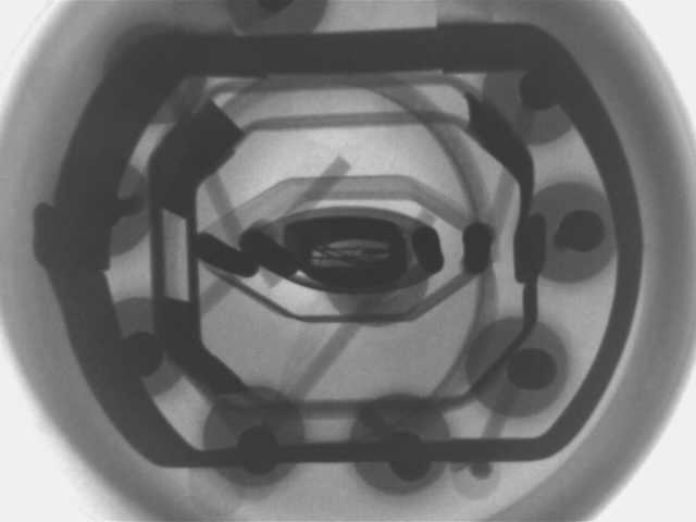
There is no alignment of screen and grid,
yet it has a beam former. So is RCA 6BQ5
a true "beam tetrode" or not?
Last edited:
Wow love this Forum, thanks guys for all the great advice. So, final PSU design would look like:
The PSU spec is 360 volts for B+,
Seperate fixed bias supply that is adjustable (LM337),
A nice wad of 6.3 VDC for the heaters.
Throw in a softstart
And finally add a standby switch that drop the heater supply from 6.3 volts to 4 VDC (ala Morgan Jones's comprehensive PS) and we are good to go.
overall design concept attached, will now go away and draw up the PSU Schema, more to follow, very soon.
Don't stabilize the bias voltage in fixed bias ultralinear or triode mode. It should vary as the main fluktuations vary the anode voltage. If you stabilize it, the anode current will be unstable and easily burning your tubes.
I even do recommend to put a zener diode around 12-15V in series vith the bias voltage supply (in the EL84 amp), to make anode current stable to all mains fluctuations.
In an EL34 30W UL-amp of my design, I even have a 24V zener in series with the bias supply, to have a slight negative anode current regulation in the output tubes. This will work over a range of +-15% variations in the mains.
That also results in a constant idle power in the output tubes and they never overheat due to high mains.
JohanB
I have XRays of several 6BQ5/EL84/7189 types.
The exception: RCA 6BQ5 was a tetrode.
Looks maybe like 6AQ5 guts inside...
I've never seen an RCA branded 7189, can't
confirm or deny any rumors about that one.
There is no alignment of screen and grid,
yet it has a beam former. So is RCA 6BQ5
a true "beam tetrode" or not?
Great picture!!
The alignment between No.1 grid and screen grid should be that they have the same pitch in the windings and the threads in the screen grid wires are in the "shadow" of the grid No1 wire threads.
So my theory was based on the very low G2 current of 1,6mA RCA showed in the fixed bias PP Class AB in the datapage, and of course that it was a RCA tube.
But I checked visually (have no X-ray) some "Westinghouse" 7189 "made in England" I have, and the were true pentodes with grid 3 wires visible ........Strange, I think there were also patent rights that contributed to the tetrode/pentode variations of the same type numbers.
Sylvania says in their papers from 1959, straight out that:
The 7189 & 7189A are beam power pentodes!!!??
7189A should be able to take up to 415V in UL mode!!
Read this 2 pages here http://frank.pocnet.net/sheets/106/7/7189.pdf
JohanB")
The 7189 & 7189A are beam power pentodes!!!??
7189A should be able to take up to 415V in UL mode!!
Read this 2 pages here http://frank.pocnet.net/sheets/106/7/7189.pdf
JohanB
Philips had the extra suppressor grid patent. The Philips associated Euro tube factories produced genuine pentodes only. The Americans sidestepped the patent obstacle by inventing the beam guided tetrode. Sometimes they called it pentode too since it was electrically equivalent and did not want to confuse the customers. In England, the Osram group devised their beam tetrode series the famous KTs. Kink-less tetrodes. Referring to the elimination of the anode current kink towards left side of true tetrode's curves chart, that a beam tetrode achieves.
The alignment between No.1 grid and screen grid should be that they have the same pitch in the windings and the threads in the screen grid wires are in the "shadow" of the grid No1 wire threads.
RCA beam 6BQ5 for whatever reason, G1 and G2 are neither the same pitch,
nor shadow aligned in any way... Visit the XRay thread, got pictures proving.
RCA beam 6BQ5 for whatever reason, G1 and G2 are neither the same pitch,
nor shadow aligned in any way... Visit the XRay thread, got pictures proving.
It would be very tricky to align the grid wires like that in the assembly line, but this is the way RCA explans the function of beam power tubes, in both writing and drawing, in their papers.
Attachments
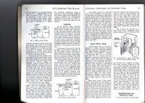
Papers are papers. I own this tube and prove w. XRay photos.
Regardless RCA theory of operations may teach us otherwise:
Grids in that particular RCA weirdo were NOT wound of similar
pitch. Not even related by an integer multiple...
I suspect to have curves more similar to real 6BQ5 pentode
there may have been no choice but the pitch RCA abused?
This was RCA attempt to clone a popular valve and evade a
patent, not to design a new theoretically ideal beam tetrode
from scratch...
Say one thing, but do another. Some "rules" got bent...
I've also peeked inside plenty of true pentodes that had
excellent gird screen alignment, regardless there was no
beam former (and no special alignment of the supressor).
What defines "beam power"? A former, or G1's shadow?
These are two entirely separate effects that happen to
work well together. But makes naming things that only
use one or the other a job for salesmen.
Last edited:
They had the EL84 from Philips, measured it, and then homed in a beam tetrode equivalent most likely. Those guys could make anything thermionic to their measure. Godfathers of vacuum. Their EL34 equivalent 6CA7 works very well in some amps, even better than a suppressor grid EL34.
- Status
- This old topic is closed. If you want to reopen this topic, contact a moderator using the "Report Post" button.
- Home
- Amplifiers
- Tubes / Valves
- 4 x EL84 in UL PP, 470 B+!! is this right