Not that complex! All you need is adding 2 resistors, bypassed with a jumper to switch so you can revert to original. I posted because you ask for it as usual. Beside I did the same gain reduction in my own OTL amp so I am quite happy and confident to share it.
Last edited:


Ok take T2 as example, 225VA, each 6c33c heater is 40W, you have 2x2=4 tubesx40=160W, so T2 has enough power to heat up all 4 output tubes. By this token, it's dual mono or stereo.
T3, 625VA, each tube max Pdissp is 60Wx4=240W, a good margin for temperature raise and duty cycle..so the data in the article is for dual mono or stereo. My amp has dual identical 300VA. a total of 600VA, same 25W, this amp (865VA) appeared to be over-rated in power supply.
T3, 625VA, each tube max Pdissp is 60Wx4=240W, a good margin for temperature raise and duty cycle..so the data in the article is for dual mono or stereo. My amp has dual identical 300VA. a total of 600VA, same 25W, this amp (865VA) appeared to be over-rated in power supply.
Last edited:
Alright, I came to the same results - almost. I also have to take into account my toroid manufacturers' physical sizes for trafos, they don't grow proportional in size to each VA step due to low number of different sizes - so for my sizes I still have some room to increase with VA within same can size. Like in case of T1, 20VA is the same size in stainless steel housing as 50VA, so I chose the bigger one.
(Wattages here are estimated maximums for sizing nothing special).
Anyway,
T1 sec1 9V, +6.3V tap
4W+10W
50VA
95x58 T1 sec2 9V, +6.3V tap
5W
body,div,table,thead,tbody,tfoot,tr,th,td,p { font-family:"Liberation Sans"; font-size:x-small }a.comment-indicator:hover + comment { background:#ffd; position:absolute; display:block; border:1px solid black; padding:0.5em; }a.comment-indicator { background:red; display:inline-block; border:1px solid black; width:0.5em; height:0.5em; }comment { display:none; }
T2 sec1 12V 90W
250VA
125x58 T2 sec2 12V 90W
body,div,table,thead,tbody,tfoot,tr,th,td,p { font-family:"Liberation Sans"; font-size:x-small }a.comment-indicator:hover + comment { background:#ffd; position:absolute; display:block; border:1px solid black; padding:0.5em; }a.comment-indicator { background:red; display:inline-block; border:1px solid black; width:0.5em; height:0.5em; }comment { display:none; }
T3 sec1 120V-0V-120V (60+60+60+60)W
400VA x 2
150x62 T3 sec2 ---
body,div,table,thead,tbody,tfoot,tr,th,td,p { font-family:"Liberation Sans"; font-size:x-small }a.comment-indicator:hover + comment { background:#ffd; position:absolute; display:block; border:1px solid black; padding:0.5em; }a.comment-indicator { background:red; display:inline-block; border:1px solid black; width:0.5em; height:0.5em; }comment { display:none; }
Due to height I can't go above 400VA so doing both sides (stereo) of T3 with 1 huge toroid can't be done for me. And the 400VA is the same in size as the 300VA one.
Hmm I think this is it then.
For your kindness of helping a beginner here and to showcase a serious DIY planning phase without circle drawing tool, I show you the results
Ok take T2 as example, 225VA, each 6c33c heater is 40W, you have 2x2=4 tubesx40=160W, so T2 has enough power to heat up all 4 output tubes. By this token, it's dual mono or stereo.
T3, 625VA, each tube max Pdissp is 60Wx4=240W, a good margin for temperature raise and duty cycle..so the data in the article is for dual mono or stereo. My amp has dual identical 300VA. a total of 600VA, same 25W, this amp (865VA) appeared to be over-rated in power supply.
I think it depends on the cores in use, downrating the transformers probably makes it easy across manufacturers core specification for the magazine article.
my concern about the Tim Mellows design is that the ef86 is 150 volts on one side and 200 volt on the other, i wonder to what extent this disparity affected performance. i was thinking using pentodes with at leasts 300volt plate voltage ratings...i was looking at the 6bn11to try...
my concern about the Tim Mellows design is that the ef86 is 150 volts on one side and 200 volt on the other, i wonder to what extent this disparity affected performance. i was thinking using pentodes with at leasts 300volt plate voltage ratings...i was looking at the 6bn11to try...
Interesting - the original schematic has notes of V4's grid at the top of the EF86 as -50V and -350V at the cathode. I've not modelled it to see if the resulting values are as documented.
Thanks to Raph's M60 design.. I seem to have turned into a circlotron fan rather than a totem.
Dear Forum members,
how picky is this OTL amp regarding matching 6S33S-V tubes ?
I have a pair from batch 'A' and another pair from batch 'B' - same manufacturer, some year difference but that's it. But same batch isn't always a guarantee for individual values being close to eachother.
Question is, if this amp tolerates some (or even a lot of) differences between tubes, or rather doesn't.
Just out of curiosity. (Everything depends on circuit topology, so that's why I'm asking). The spread between real tube values compared to nominal values is kind of high for 6S33S tube types as I've learned.
Dear Forum members,
how picky is this OTL amp regarding matching 6S33S-V tubes ?
I have a pair from batch 'A' and another pair from batch 'B' - same manufacturer, some year difference but that's it. But same batch isn't always a guarantee for individual values being close to eachother.
Question is, if this amp tolerates some (or even a lot of) differences between tubes, or rather doesn't.
Just out of curiosity. (Everything depends on circuit topology, so that's why I'm asking). The spread between real tube values compared to nominal values is kind of high for 6S33S tube types as I've learned.
OTL "Totem pole" designs like this have a number of balance points.
Firstly - the phase balance, resulting in a differential with zero DC offset. LTP output and possibly driver configuration is used to manage this balance Two ways this impacts - if the two phases aren't amplified with the same distortion then you get the difference output.
Also for direct coupled, DC offset difference messes with the biasing that impacts the differential output.
Second - the Rplate match between the tubes as mu = gm * Rplate, where gm = Iout change / Vin change. So as Rplate changes both in manufacture and time, it may become unbalanced over time
If you test the grid voltages and the current output you can get a graph of the plate resistance (it's not linear) - those graphs should be ideally equal. This would mean the two phases would then output equally and thus be in balance (see point one above). The common noise would then be equal and cancel.
The second is the normal one that people have issues with and what you're discussing.
If you imagine this: if the tubes are unbalanced the sound out will have distortion and if direct connected could have DC supplied to the speakers.
Ubalanced output tubes will give increased distortion. In our amplifiers we match output tubes to within 2V difference in grid voltage for same idle current.
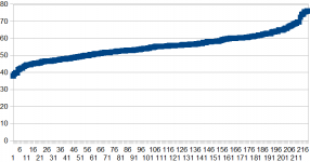
6C33C tubes spread quite a lot so if pays off to have many tubes to choose from, attached is a plot of grid voltage for >200 tubes, as you can see grid voltage goes from below 40V to above 75V, all can be useable if you select 2 that don't differ to much.
The reason of the wide spread in 6C33C is that high Gm tubes have very small inter electrode distances so any tolerance have much higher effect than in a more normal lower Gm tube
Attachments
If you imagine this: if the tubes are unbalanced the sound out will have distortion and if direct connected could have DC supplied to the speakers.
This is why this amp has quite a bit of global NFB - about 26 dB in the original version - which tries to fix both issues to a certain point.
GnFB is DC (the 1M resistor from speaker to 1st grid) which also acts as a DC servo.
I did a quick simulation in which I added a 10 ohm resistor in the cathode of only one of the output tubes. This should have a dramatic effect on the 6C33C as it not only affects DC characteristics but also completely changes the curves meking it a weak tube. Of course the max output drops to some 15W but I was looking for changes in distortion at much lower levels of 5W or so. After readjusting the quiescent current with the pot to the previous 200mA here's the result:
THD went up from 0.2% to 0.4% and DC across the speakers increased by 2mV.
So I would say not too picky on tube balance - with the design as is with 54dB of open loop gain , 26dB of FB and 28dB closed loop gain (sensitivity 0.5V).
Now will this change when we reduce the open loop gain ? e.g. by KOONW's method, because now the FB is potentially less efficient when it comes to error correction.
Again a quick sim, with open loop gain 35dB, same 26dB FB and 9dB closed loop gain (sensitivity 5V, R1, R2 now 330k). Your target forgain reduction maybe ...
DC unbalance with degraded tube now 25mV - FB less effective due to lower open loop gain - which is correctable with the balance pot.
THD with degraded tube was again 0.4%, because I kept the global FB the same 26dB.
It seems that the global FB is quite effective to deal with distortion caused by output tube unbalance ,
but reducing the open loop FB degrades the effectivity of the DC servo mechanism as expected.
Last edited:
Well, I had to read this a couple of times 'til I got it. Clever. And I understand the issue.. Hmm.
Is there any way at all, to preserve this error-correction capability, while aiming for somewhat lower gain and let's say, 6V input sensitivity ?
- with the existing circuit ?
- by replacing maybe ECC83 with ECC88 ?
- any other ideas ?
Of course I'd like to make the least painful compromise - will it be a simple input signal - weakening voltage divider then, what do you think ?
It's still better than driving a 0.5V input with all that power from DAC.
Thanks Gentlemen, amazing. Can't wait for the toroids to arrive - and all the other parts. Mid december, the trafo manufacturer has resin supply issues (they're out of resin and supply is delaying by 2 weeks).
Seemingly, not only chips are affected by the global shortage..
Seemingly, not only chips are affected by the global shortage..
If that's working fine, maybe I'll keep this in mind too.
- - - - - - -
Are there ANY safety precautions regarding type, placement and manual setting of RV2 & RV3 ?
Will 2 normal little blue precision trimpots just do the trick (I used to use these for my low-voltage regulator IC-s) or shall I choose tougher kind of trimpots ? Just because of voltage, when I look at the schematics.
Balancing you can use a DC servo.
The output is low pass filtered (to find the DC offset) using an Opamp that then alters the bias balance to cancel the offset.
Have a look at the circuit again:
The DC servo is already built in because the FB from output to input tube grid is DC, the 1 Mohm resistor ... and the whole amp is DC coupled, too ... this amp actually IS a tube based op-amp ...
its just that when you reduce open loop gain the precision of that built in servo is also reduced.
Doubling or nesting servo loops is maybe not so good an idea as they might fight each other ...
Last edited:
- Home
- Amplifiers
- Tubes / Valves
- OTL designed by Tim Mellow with 4 6C33C?