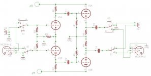
A line amp I'm going to build will have both SE and balanced input and output. The input and output should be selected individually, either SE or balanced. That is, the amp should work either SE to SE, balanced to balanced, SE to balanced or balanced to SE – all by means of a switch at the input and another switch at the output.
The switching schematics is attached.
Will this circuit work properly under all input and output conditions?
The switching schematics is attached.
Will this circuit work properly under all input and output conditions?
Attachments
Will this circuit work properly under all input and output conditions?
No.
Thanks.
What changes are needed for proper operation under all conditions?
Are changes needed on the input, or output, or both?
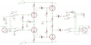
I made one change, added load resistor for SE output.
Attachments
I would start from drawing values on the schematic. Most probably for proper operations under all conditions it is better to replace R3 by CCS.
However, you have to keep in mind that amplification factor will depend on which input and which output were used. I don't know, is it proper operations, or not, according to your requirements.
However, you have to keep in mind that amplification factor will depend on which input and which output were used. I don't know, is it proper operations, or not, according to your requirements.
Thanks.
The schematic attached here is a simplification of the actual circuit. R3, R8 and R9 in the attached schematic, each represent a CCS.
I'm aware of the changes in amplification factor between SE and balanced operation. Those changes will be adjusted in the final circuit by switching resistors.
Other than changes in amplification, will this circuit operate properly under all input and output conditions?
Why are you bothering with the switching? You don't need it...
Switching is needed, at least on the minus of the signal.
Why? At the most you only need to tie the unused input to ground if you are running single-ended input. It makes no difference at the output. Usually the way you do the input is with a U-shaped jumper that installs between pin 1 and pin 3 of the XLR.
If not to ground unused input of a diffpair there will be higher noises and worse THD measurements. However, if not to use a diffpair at all noises will be lower, sound cleaner, but may be THD figure not so nice looking.
I would definitely use a single tube and a pair of transformers instead of what is drawn, however if to speak about high-end approach. Otherwise, LEDs under all tubes would be nice.
")
I would definitely use a single tube and a pair of transformers instead of what is drawn, however if to speak about high-end approach. Otherwise, LEDs under all tubes would be nice.
I prefer extra tube(s) over transformer(s).
Anyhow, the schematic I posted is a highly simplified drawing of one of Allen Wright's designs, posted on his website. As I wrote above, there are CCS's on the cathodes. In any case, I'm going to stick to Allen Wright's design to the letter, that's for sure. This is because of both I can see the benefits of the design and the reviews Allen's amps received. Modifying the amp design itself is out of the question for me.
My only question was about input and output switching, for the topology given in the schematic I attached. Though the schematic is highly simplified, to topology is basically the same.
Please check again. Some switching is necessary both on input and output.
I don't agree. You are making this a lot harder than it needs to be. Seriously. You don't need to drive the ground of the RCA. Just let that side float if its not going to be used. Set the RCA ground to circuit ground, and permanently wire the outputs of the circuit to the XLR. Tie pin 2 to the RCA and its all good, unless you prefer to tie pin 3 to the RCA.
You can do something similar at the input. I've done this for 21 years; as far as I know I built the first fully differential tube preamps. BTW, to avoid issues with THD and gain differences, you will need an effective CCS for each gain stage. Then the circuit will not care how you drive it.
At the output switching can be avoided by connecting the RCA shield to the ground permanently and letting the (-) side of the amp float on SE output.
At the input, on the topology shown, for SE input, the (-) input side of the amp would better be switched to ground for noise reasons (it's an MC phono stage).
Once again, on the actual circuit each and every cathode is driven by CCS. On the input LTP, there is a common CCS to both tubes.
At the input, on the topology shown, for SE input, the (-) input side of the amp would better be switched to ground for noise reasons (it's an MC phono stage).
Once again, on the actual circuit each and every cathode is driven by CCS. On the input LTP, there is a common CCS to both tubes.
At the input, on the topology shown, for SE input, the (-) input side of the amp would better be switched to ground for noise reasons (it's an MC phono stage).
Once again, on the actual circuit each and every cathode is driven by CCS. On the input LTP, there is a common CCS to both tubes.
Yes, you can't let the unused input float. However, especially if you are using a low-level source such as LOMC, you don't want to trust that to a switch. The least amount of extra wiring you can install will help you with RF and the least number of mechanical contacts (switches and connectors) that you have in the circuit the better. This is why you see lots of high end tone arms that don't have a removable headshell.
As you probably already know, nearly all phono cartridges are balanced sources, so in my mind there is no argument for the RCA input connector at all, unless you plan to use someone else's turntable for a short while. You really want to take advantage of the CMRR by having your tone arm cable run balanced all the way. To have that switch in there for what is ultimately going to be a temporary connection seems like a high price to pay.
Kudos for the attempt- IMO balanced operation for phono is the way to go!
(it's an MC phono stage).
I hope, not the first one?
By the way, my partner in Maale Shomeron can help you ending all sufferings. He has great designs regarding MC, MM, and power amps.
Yes, you can't let the unused input float. However, especially if you are using a low-level source such as LOMC, you don't want to trust that to a switch. The least amount of extra wiring you can install will help you with RF and the least number of mechanical contacts (switches and connectors) that you have in the circuit the better. This is why you see lots of high end tone arms that don't have a removable headshell.
As you probably already know, nearly all phono cartridges are balanced sources, so in my mind there is no argument for the RCA input connector at all, unless you plan to use someone else's turntable for a short while. You really want to take advantage of the CMRR by having your tone arm cable run balanced all the way. To have that switch in there for what is ultimately going to be a temporary connection seems like a high price to pay.
Kudos for the attempt- IMO balanced operation for phono is the way to go!
Indeed, the cable coming out from my record player is balanced, though right now it ends with RCAs. I intend to change the connectors to XLR, once the amp will be built. For phono I'll have only XLR inputs. For trying others' players, I'll prepare external RCA to XLR adaptors.
The same will apply to the tape head pre-amp.
As for the line level inputs, I wonder what the better approach is?
I hope, not the first one?
By the way, my partner in Maale Shomeron can help you ending all sufferings. He has great designs regarding MC, MM, and power amps.
It is the first phono stage I'm going to build, but not the first pre-amp.
My guts feeling compels me to stick to Allen Wright's designs, both for pre-amp with phono stage and for power amp (mono blocks). Allen Wright's phono stage can be switched to either MM or MC.
I mean, it is the stage driven directly by a MC cartridge?
Oh mine gott...
Yes, the stage is driven directly by MC cartridge, though it's a pair of FETs cascoded by a pair of tubes, the FETs are fed by a common CCS.
Dine Gott in himell has nothing to do with it,
You can see Allen designs here: Schematics .
You can see Allen designs here: Schematics .
You as well can communicate with him through PM, if don't want our opinions.
- Status
- This old topic is closed. If you want to reopen this topic, contact a moderator using the "Report Post" button.
- Home
- Amplifiers
- Tubes / Valves
- SE-BAL-SE Switching