Hello everyone. I'm going to try this forum and see if I can get pointed in the right direction.
First let me say I've never built a tube amplifier but I have fixed a few. I know enough about electronics to design my own transistor analog circuits but I've never worked with tube design.
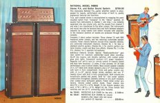
Long story short. I picked up a National N6800 stereo PA amplifier and nursed it back to semi-working condition. It's from 1968 and cost $750 1968 dollars. It's rusty and noisy but I just needed to know the tubes and transformers are ok. It uses 4 6L6 outputs push-pull and 12AX7s scattered around for preamp, reverb loop, and a distortion channel for a guitar input apperently. It's rated at 70w rms (total).
What I would like to do is gut this amp for it's major components and build a stereo hifi amp out of it. 35w/ch is plenty of power for my Wharfdale bookshelf speakers. I've found so many schematics online that I'm drowning in them and when I think I found a good one I read on and hear how this component should be changed to that and yadda yadda but no update to the schematics!
Can someone point me in the direction of a fairly good quality 6L6 push-pull amp schematic that uses 12AX7s in the front end? Did I say good and 12AX7 in the same sentence? Well it's good enough for me. I can clean things up alot with proper power supply filtering, grounding, signal paths, and good components. I wouldn't mind having a bass/trebble adjustment either but I could copy that from another schematic and insert it if I have to. So, if anyone has built something like I'm talking about and has -finished- schematics, I'm all ears.
By the way, these output transformers are only 5 wire and I assume 8ohm output. No linear taps for me. =(
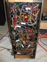
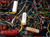
Attached are a few pics of my poor old amp.
First let me say I've never built a tube amplifier but I have fixed a few. I know enough about electronics to design my own transistor analog circuits but I've never worked with tube design.
Long story short. I picked up a National N6800 stereo PA amplifier and nursed it back to semi-working condition. It's from 1968 and cost $750 1968 dollars.
It's rusty and noisy but I just needed to know the tubes and transformers are ok. It uses 4 6L6 outputs push-pull and 12AX7s scattered around for preamp, reverb loop, and a distortion channel for a guitar input apperently. It's rated at 70w rms (total).What I would like to do is gut this amp for it's major components and build a stereo hifi amp out of it. 35w/ch is plenty of power for my Wharfdale bookshelf speakers. I've found so many schematics online that I'm drowning in them and when I think I found a good one I read on and hear how this component should be changed to that and yadda yadda but no update to the schematics!
Can someone point me in the direction of a fairly good quality 6L6 push-pull amp schematic that uses 12AX7s in the front end? Did I say good and 12AX7 in the same sentence?
Well it's good enough for me. I can clean things up alot with proper power supply filtering, grounding, signal paths, and good components. I wouldn't mind having a bass/trebble adjustment either but I could copy that from another schematic and insert it if I have to. So, if anyone has built something like I'm talking about and has -finished- schematics, I'm all ears. By the way, these output transformers are only 5 wire and I assume 8ohm output. No linear taps for me. =(
Attached are a few pics of my poor old amp.
Attachments
Looks like a fun project. The power transformer looks usable, and the choke looks good, but those output transformers look pretty dicey (and small). They're easily replaceable though. Nothing wrong with 12AX7's.
You'll need to determine the power supply voltages so you can find a suitable schematic. Remove all the tubes and map the transformer output voltages. At the very least you will find 1 high voltage winding (3-400 volts) and one or two 6.3 volt windings for the tube heaters. Those will be easy to find by following the wires from the tube socket heater pins. Check the datasheet tube pinouts.
(...and be careful! This ain't no +/-36v BJT circuit.)
..Todd
Last edited:
Welcome. First thing I would do is check that the output trannies are actually an 8 ohm output, because if they aren't, the plan will go tits up. To check them, run a signal generator at say 100hz into the secondary winding and measure the voltage across the primary winding. This will give the turns ratio, usually somewhere between 20:1 and 30:1. Then square that to get the impedance ratio, which is 400:1 for a 20:1 turns ratio, or 900:1 for a 30:1 turns ratio for example. In the case, for example, of a 20:1 turns ratio, which is a 400:1 impedance ratio, an 8 ohm speaker would give a reflected impedance of 8 x 400 = 3200 ohms across the primary. You might want a reflected primary impedance of between 5K and 8K for 6L6.
Can't help you with a schematic sorry, maybe best if you post one you're interested in, and let us all rip it to bits, I mean, er arr sorry, give some advice on it.
Can't help you with a schematic sorry, maybe best if you post one you're interested in, and let us all rip it to bits, I mean, er arr sorry, give some advice on it.
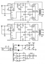
Thanks for the input. I know electronics safety so no worrys. I unfortunately do not own a signal generator. I do have a scope though. I take that back. I have a signal generator but it's on a musical scale. It's used for tuning subwoofers. How to use that for calculating inductors is above me. My electronics math is limited to things like ohms law. That's about it. I have a schematic someone sent me today but it won't work. Not as it's drawn anyways. Take a look at the heater supply for the 12ax7s and you'll see what I mean.
I have a schematic someone sent me today but it won't work. Not as it's drawn anyways. Take a look at the heater supply for the 12ax7s and you'll see what I mean.Attachments
Last edited:
Oh I forgot to ask. The choke? Are you refering to the small transformer near the bottom of the image of the top of the chassis? It has 4 wires. It's connected to the reverb circuit I believe. At least one of it's wires it connected directly to one of the wires to/from the spring box. Another to HV B+. It almost looks as if it modulates the B+ supply to/from a driver tube with the signal from the spring box.
EDIT - What's happening to my posts? They are there then they're not? There was a post before this one but it vanished.
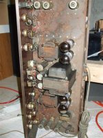
EDIT - OK it's back. And here's another pic of the output sockets. I labeled the output transformer as 'opt', the primary as 'pri', the secondary as 'sec', and center tap as 'ct'.

EDIT - What's happening to my posts? They are there then they're not? There was a post before this one but it vanished.
EDIT - OK it's back. And here's another pic of the output sockets. I labeled the output transformer as 'opt', the primary as 'pri', the secondary as 'sec', and center tap as 'ct'.
Attachments

Last edited:
You could use a little 10 or 12V AC plugpack (wall-wart in America) and run that into the secondary instead of a sig gen. Only diff is it will be 50 or 60Hz. Not really a worry.
It looks like that design is using the 12AX7 heaters as cathode loads for the 6L6, it is unusual to do it that way these days, with all the different 6L6 variants who knows where the bias will end up at.
Edit: your pic - it all looks in pretty good condition underneath!
It looks like that design is using the 12AX7 heaters as cathode loads for the 6L6, it is unusual to do it that way these days, with all the different 6L6 variants who knows where the bias will end up at.
Edit: your pic - it all looks in pretty good condition underneath!
Last edited:
You could use a little 10 or 12V AC plugpack (wall-wart in America) and run that into the secondary instead of a sig gen. Only diff is it will be 50 or 60Hz. Not really a worry.
It looks like that design is using the 12AX7 heaters as cathode loads for the 6L6, it is unusual to do it that way these days, with all the different 6L6 variants who knows where the bias will end up at.
Edit: your pic - it all looks in pretty good condition underneath!
I have a small 12v ac transformer I can use for a 60hz signal.
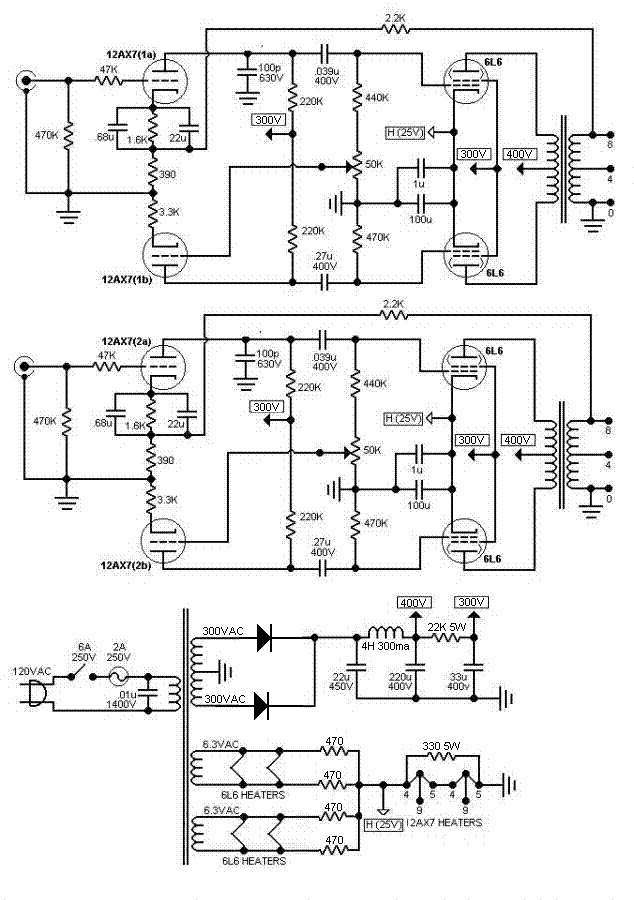
It wasn't so much the cathode load. I sort of follow that. It's the pins themselfs. 4, 5, and 9. In that schematic they are all tied together. lol. One has to assume there's heaters off 4 and 5 but 9 should be left disconnected. They just drew it wrong is all.
I was happy when I pulled out the chassis and found the insides clean and intact. I was expecting all the wires to be chewed.
I've started transfering my amp's wiring, for the 12ax7 driver and 6l6 pair, onto a drawing. I intend to gut it then rewire one channel just to see how it sounds. I'll post what I copied first to get some opinions incase I drew something wrong. There seems to be some differences between the left and right channels. If you read that manual I posted, the amp has different functions for each channel. Tremolo, for example, only drives the right channel. As does the reverb and the "buzz" function. Right has a line-in but it seems the right channel is mainly for guitar. The left channel has 2 mic inputs and also a line-in. There's a mono switch if you wanted to make all effects/inputs play through both speakers. I guess my point is the preamps are not symetrical in the least.
I forgot to mention. The main and output transformers I'm using are all from this amp using the 6L6s and 12AX7s. I shouldn't have a problem if I keep everything together and use the same values of resistors in the psu to keep the voltage steps as they are now. Tweaking can be done later. First thing is to eliminate the ** and get one mono amp working.
4, 5, and 9. In that schematic they are all tied together. lol. One has to assume there's heaters off 4 and 5 but 9 should be left disconnected. They just drew it wrong is all.
Actually, that's just the way heaters are drawn on schematics. The inverted V ( /\ ) represents the actual heater filaments, so they are actually all connected to the pin numbers shown, not shorted together. For some 12v tubes (like 12AX7), they provide a "center tap" on the filament so you can use 2x 6.3 v to power it. If you disregard the center tap (pin 9) you will need 12.6 volts, instead of 6.3.
The small transformer for the reverb circuit, looks exactly like a choke. In the schematic you provided, the choke is the 4H/300mA inductor in the power supply.
Drawing out the existing circuit is an excellent plan. If you decide to dump all the effects circuits (which I assume you probably will eventually), you'll need that schematic.
Don't expect all those electrolytics to be working well. You should probably replace them. In fact you should probably replace all the capacitors.
..Todd
Last edited:
Actually, that's just the way heaters are drawn on schematics. The inverted V ( /\ ) represents the actual heater filaments, so they are actually all connected to the pin numbers shown, not shorted together. For some 12v tubes (like 12AX7), they provide a "center tap" on the filament so you can use 2x 6.3 v to power it. If you disregard the center tap (pin 9) you will need 12.6 volts, instead of 6.3.
That was my take as well, the two 12ax7's are then in series needing 25v across them which appears to be provided by the 6l6 cathode bias, or is the cathode bias
Still scratching my head on this one
Any way welcome and best of luck in your build.
p.s. may reduce heater hum as well by creating artificial heater centre tap.
Last edited:
Lazzer: I would try to determine the primary impedance of your output transformers first, as mentioned above.
If you don't have SG taps, then consider a triode design, lower power but nice distortion spectrum.
Are you Married to the 12AX7's and 6L6's? Once you determine the output transformer primary impedance there will be a number of possible schematics around. You may also be able to run EL34's....
If your power supply is a CLC (cap-choke-cap) input, then you can adjust the B+ voltage a bit by varying the value of the first cap. If you a planning on vacuum tube rectification, you can adjust the B+ voltage by swapping rectifiers (5u4 drops around 70V and 5AR4 drops around 30 volts). You can also use SS rectifiers to increase voltage if needed, so lots of adjustments there.
The output transformers appear to be a bit small, so a triode circuit may be the best bet.....although the miller C of trioded output tubes may be a bit much to drive with 12AX7's
Last edited:
Better not to limit your options just yet until you find out more about your "iron" , eg are your output transformers tapped for ultra linear as boywonder asks
The output transformers only have 5 wires. 3 in, 2 out. In that close-up of the bottom of the chassis I circled them. They are not ultra linear.
There are no chokes in the 6800's power supply. The 6800 also uses SS rectification. I plan to do the same.
Yes I'm married to the 12AX7 and 6L6 because it's what I have and it was working in the 6800. The only reason I'm building the amp is because I have the parts. I don't mind forking out a few bucks for caps and resistors but I have no intention of buying new output transformers and tubes. If I had the cash to spare I'd just buy a kit.
Last edited:
Probably the easiest design to do would be a simple common cathode input to cathodyne phase splitter driving the output tubes and taking feedback from the output transformer secondary to the cathode of the input tube (may not need FB in triode mode). Sort of like the Williamson without the extra driver stage. Should be lots of examples out there to look at. Since you have a scope grocking out the feedback should be no problem. Or you could go more Mullard style by using LTP instead of cathodyne.
You may have trouble finding new designs using 12AX7 as it is not currently in vogue but a lot of vintage amps used them quite heavily so check out old Eico and similar for some possibilities. One thing about the 12AX7 is that it has quite a bit of gain and would be a bit much for no feedback designs but if you are going to go pentode mode you really will need some kind of feedback so should not be a big problem. The other thing is that the 12AX7 really likes a fairly large plate resistor so it would be easier to do a good cathodyne I would think rather than LTP but I could be wrong about that.
Another option would be to use an extra 12AX7 as a cathode follower after the PI to provide better drive to the output tubes. Yes a 12AX7 is not a great CF but a 12AX7 as a CF would I think be a more capable driver than having the same tube trying to drive the outputs directly from its plate (esp. when approaching overload).
Probably the easiest design to do would be a simple common cathode input to cathodyne phase splitter driving the output tubes and taking feedback from the output transformer secondary to the cathode of the input tube (may not need FB in triode mode). Sort of like the Williamson without the extra driver stage. Should be lots of examples out there to look at. Since you have a scope grocking out the feedback should be no problem. Or you could go more Mullard style by using LTP instead of cathodyne.
You may have trouble finding new designs using 12AX7 as it is not currently in vogue but a lot of vintage amps used them quite heavily so check out old Eico and similar for some possibilities. One thing about the 12AX7 is that it has quite a bit of gain and would be a bit much for no feedback designs but if you are going to go pentode mode you really will need some kind of feedback so should not be a big problem. The other thing is that the 12AX7 really likes a fairly large plate resistor so it would be easier to do a good cathodyne I would think rather than LTP but I could be wrong about that.
Another option would be to use an extra 12AX7 as a cathode follower after the PI to provide better drive to the output tubes. Yes a 12AX7 is not a great CF but a 12AX7 as a CF would I think be a more capable driver than having the same tube trying to drive the outputs directly from its plate (esp. when approaching overload).
What?
Attached is what I think I've correctly copied from the 6800. Ignore the voltages for now. I just threw in some valuse. I haven't measured it yet.
Attachments
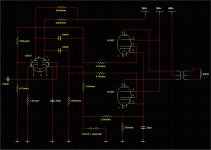
Hmmm... you may have some of the connections not quite right as the 12ax7 pin 7 grid is getting a signal only from its own plate. I suspect you have the plates switched. If you change those around then you have a paraphase splitter which though not in vogue in current hi-fi circles has been used to good effect an many console amps so you may not need to change much at all other than updating some components.
I am getting a little confused with the cathodes there but it may be that they are taking feedback from the cathode of one of the output tubes to the cathode of one of the input tubes. You might want to change that and use feedback from the secondary of the output transformer instead to help compensate for transformer limitations so long as you are not trying for tremendous bass response which could overload things trying to correct for bass limitations.
hmm... that can't be feedback from the output cathodes as they are sharing a cathode resistor.
Interesting unit.
Last edited:
Hmmm... you may have some of the connections not quite right as the 12ax7 pin 7 grid is getting a signal only from its own plate. I suspect you have the plates switched. If you change those around then you have a paraphase splitter which though not in vogue in current hi-fi circles has been used to good effect an many console amps so you may not need to change much at all other than updating some components.
I am getting a little confused with the cathodes there but it may be that they are taking feedback from the cathode of one of the output tubes to the cathode of one of the input tubes. You might want to change that and use feedback from the secondary of the output transformer instead to help compensate for transformer limitations so long as you are not trying for tremendous bass response which could overload things trying to correct for bass limitations.
hmm... that can't be feedback from the output cathodes as they are sharing a cathode resistor.
Interesting unit.
Copying this stuff isn't easy.
 It's getting to the point where I'm asking. Do I even need a tube amp. heh.
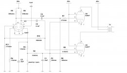
- Status
- This old topic is closed. If you want to reopen this topic, contact a moderator using the "Report Post" button.
- Home
- Amplifiers
- Tubes / Valves
- 6L6 / 12AX7 push-pull