Yep, looks better. You see that the output of the right triode is reduced by the voltage divider of R10 and R11 and fed to the left hand triode which amplifies it back to its original level and inverts it to drive the anti-phase output tube. There is no NFB here as drawn so we might want to add some. Also replace coupling caps with quality film caps and maybe enlarge some (these will start rolling off just below 20Hz so a little more margin would be nice). After recap we could try a little plate to plate feedback (I suppose about 200K to 300K) between output tube plate and its drivers plate. Other more skilled designers here could probably help with that. The other option would be global FB but I am not sure how we would go about that in a paraphase circuit.
This should be a fun project.
This should be a fun project.
Yep, looks better. You see that the output of the right triode is reduced by the voltage divider of R10 and R11 and fed to the left hand triode which amplifies it back to its original level and inverts it to drive the anti-phase output tube. There is no NFB here as drawn so we might want to add some. Also replace coupling caps with quality film caps and maybe enlarge some (these will start rolling off just below 20Hz so a little more margin would be nice). After recap we could try a little plate to plate feedback (I suppose about 200K to 300K) between output tube plate and its drivers plate. Other more skilled designers here could probably help with that. The other option would be global FB but I am not sure how we would go about that in a paraphase circuit.
This should be a fun project.
Q: The right triode drives the lower 6L6 and the left triode is inverting and drives the top 6L6? The way it looks now does it look like it will opperate aside from not having any feedback? Do you think it's possible the feedback could be handled somewhere in the preamp stages? I'll see if I can find anywhere the opt might get routed back to that area.
Q: Does there need to be a cap at the input or can I feed a signal directly into the gate?
The voltages shown are the voltages I measured with the tubes in place. They're really driving those 6L6s arn't they? That would lead me to believe the opt's primary resistance is 'high-ish'.
I was playing it today through my Magnavox cubes and it really puts out some power. There is very little change in tone as the volume is increased. If anything, I think the low end thickens up a bit. I like how it sounds except for the tone control. The first 1/4 turn of trebble is very bright and detailed but the next 3/4 boosts harsh mids. The bass is also lacking. Probably to minimize the onset of distortion. Just right for a PA though.
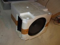
Here's a pic of the cubes I'm testing this with. They were yanked from a console stereo. I like how they sound with the tube amp. I might just build them into a wooden enclosure, add a tweeter, and shape the crossover to use the horn as a midrange.
Attachments
Last edited:
That switch on the cathode is interesting. When it is not in the closed position, it raises the bias on the input triode to cut it off effectively muting the amp. What if you swap the phase splitter and input triodes cathode connection, the switch would cause the phase splitter triode to cutoff making it a single ended amp.
That switch is the stand-by switch. I'll probably go about it differently then they did. Yes it does mute the amp but not in the typical fashion. Normally the stand-by switched removes B+ doesn't it? This amp is full of oddities.
I've started removing stages. The mic stage is now removed. It used a single 12AX7 for 2 mic preamps. The reverb stage is bypassed. I'm working on removing the tremolo stage now. The gain/mono switchs are also removed. I'm thinking this would be easier to do a gut/rewire for testing rather then working around everything. I just don't want to disconnect something that I shouldn't unless I know I have a good schematic to reference.
Can anyone tell me for sure that the one I posted last is correct?
Voltages look fine. Not over doing it in that respect. Would have to look at data sheet to see about bias current. Lack of FB would only effect sound quality and gain. It will function fine as is just won't sound as good as it could. Another thing you could try is to triode strap (disconnect screen from power supply and connect screen to plate with a 100 ohm resistor). Will reduce power output but may sound fine without FB.
Input cap is probably not necessary but would protect source in case of short in the tube or wiring. Also I note that you don't show the grid leak resistor for that triode. There should be a resistor from grid to ground. Need to make sure that that resistor hasn't drifted too high in value.
Personally I would not gut and rewire unless you want to do your own design from scratch. Too easy to mess something up.
Voltages look fine. Not over doing it in that respect. Would have to look at data sheet to see about bias current. Lack of FB would only effect sound quality and gain. It will function fine as is just won't sound as good as it could. Another thing you could try is to triode strap (disconnect screen from power supply and connect screen to plate with a 100 ohm resistor). Will reduce power output but may sound fine without FB.
Input cap is probably not necessary but would protect source in case of short in the tube or wiring. Also I note that you don't show the grid leak resistor for that triode. There should be a resistor from grid to ground. Need to make sure that that resistor hasn't drifted too high in value.
Personally I would not gut and rewire unless you want to do your own design from scratch. Too easy to mess something up.
Grid leak resistor from 12ax7's pin-2 to ground? I noticed those on the mic-pre that I just ripped out. I'll use those resistors as a start. Say 1m or so? Probably lower so the input gain won't be to high. Hell even 1k would probably work for line level signals. I think I'll keep the input capacitor to protect connected devices though. Good thought.
I'm removing the polarity switch and adding a grounded cord. One leg of the AC input to the power transformer has a cap tied to ground. Would connecting that cap in parallel with the line do much for noise? It's .01uf 1400v. I think I'll leave it out for now. In the final design I'm adding a Corcom type filter anyways. I've used them in the past and they do a great job of supressing input spikes. Many of the lights in the house are those fluorescent replacement bulbs and they can sure drop a spike into the house wiring when you turn them off.

I'm about to fire this up again. -looks at the pile of guts on the floor- I hope it doesn't miss any of that.
It still works. The noise levels are much much lower now. I'm still getting a hum and a slight buzz from the left channel. The hum could just be dry ps caps and the buzz may be a ground I missed. I've been trying to tie them together. Everything is grounded to the chassis through rusty rivits and I've been trying to tie them together with wire inside.
I still haven't had much luck finding a hifi amplifier using 12ax7s and 6l6s other then the first schematic I posted. Can someone chime in and explain the 25v cathode bias and the heaters? Could I just conenct the cathodes to ground with a resistor and use normal heater supply? And what is the 50k pot for?
Here's that schematic again.
Last edited:
here's an option for you - although you'd need to rework the values.
Taken a little further you end up in the self-splitting world of the odd-watt. Again, proof of concept only - you'd have to do your own numbers. Also, limited to Class A only.
Taken a little further you end up in the self-splitting world of the odd-watt. Again, proof of concept only - you'd have to do your own numbers. Also, limited to Class A only.
Last edited:
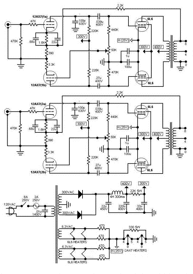
The idea, as far as I understand, is that the 25V cathode bias is achieved by the current flowing through the two 12AX7's heaters in series. The heaters want 150mA and the other 330 ohm 5W resistor in parallel will take 75mA at 25V so say around 225mA all up for the 4 output tubes, around 56mA bias each. Yes you could just power the 12AX7 heaters from the transformer and use resistors for bias. The 50K pot is to balance the levels of the two out of phase signals driving the output tubes.
A 12AX7/6L6 schematic 6V6 amp - schematic options I built that one and for a simple schem with 12AX7 sounded surprisingly good. I ran it pentode mode, like your amp, not ultralinear. No global feedback. It would be one way of getting a good starting point and use what you have. You can always improve it further down the track.
A 12AX7/6L6 schematic 6V6 amp - schematic options I built that one and for a simple schem with 12AX7 sounded surprisingly good. I ran it pentode mode, like your amp, not ultralinear. No global feedback. It would be one way of getting a good starting point and use what you have. You can always improve it further down the track.
Any benefit the 12AX7's do not become emissive until after the 6L6?
Any benefit from 6L6 surge current while the AX7 filiaments are cold?
This looks like a "bad" thing, but is it also a cathode rejuvenator that
takes 6L6 cathode up to the limit of emission while plate and screen
are still cold enough to handle it? Does this abuse cycle ruin 6L6, or
make it last longer?
Pure science fiction here, I'm guessing in the dark. There may not be
any benefit except that its cheap and saves 150mA on the winding.
Last edited:
There may not be
any benefit except that its cheap and saves 150mA on the winding.
The current has to come from somewhere.
The design is thought provoking worthy or not.
I for one would like to know the answers to Kenpeter's questions - any takers
The surge / different warm up times are irrelevant. The valves won't care about a little surge current.Any benefit the 12AX7's do not become emissive until after the 6L6?
Any benefit from 6L6 surge current while the AX7 filiaments are cold?
The great value in powering the 12AX7 heaters from the power valve cathodes is that it neatly eliminates heater hum in the preamp, without the expense of a dedicated DC heater supply. Incidentally, this method of heating the valves is affectionately known as the "free lunch"!
The idea, as far as I understand, is that the 25V cathode bias is achieved by the current flowing through the two 12AX7's heaters in series. The heaters want 150mA and the other 330 ohm 5W resistor in parallel will take 75mA at 25V so say around 225mA all up for the 4 output tubes, around 56mA bias each. Yes you could just power the 12AX7 heaters from the transformer and use resistors for bias. The 50K pot is to balance the levels of the two out of phase signals driving the output tubes.
A 12AX7/6L6 schematic 6V6 amp - schematic options I built that one and for a simple schem with 12AX7 sounded surprisingly good. I ran it pentode mode, like your amp, not ultralinear. No global feedback. It would be one way of getting a good starting point and use what you have. You can always improve it further down the track.
Can you re-post that schematic here? I can't view it.
You shouldn't have to add a grid leak resistor it should already be there. There has to be a DC path to ground from the grid or it wouldn't bias up right. As to a value 1Meg was common but I think it is a bit high for best noise performance something in the 200k to 500k range would seem more appropriate to me. A value of 1K would be too low. The grid leak resistor won't effect gain until it gets too low. If you have a source with 1K output impedance a grid leak of 1K would reduce your output by 3dB compared to something say 10 times higher. Now if add a volume control it will be in parallel with the grid leak. In that case a largish value approaching 1meg would be fine as it would have minimal loading on the pot but still provide a safety ground reference if the pot wiper goes open.
Yep replacing the PS caps is something that should be done early.
As to that schematic in a quick perusal it doesn't look much different than what you have. You could easily modify to that circuit. I wouldn't bother copying the output tube bias using the 12AX7 heaters. A clever trick but no audio advantage over what you have. The 50K pot is a useful addition as it adjusts the balance of the phase splitter. You can use it to adjust for lowest distortion (or maybe some added HD2 if you want a more classic SE HD spectrum).
Notice that they use a 470k grid leak which is in the range I suggested. That mess of caps and resistors in the cathode along with the 2.2k resistor from the OPT secondary comprise the negative feedback that I have been talking about.
It looks like that schematic is pretty useful in your case as it is so similar to your starting point.
There's also a 47k in series. Is this required?
Between the two schematics, the one I drew and the one with the goofy cathode heaters, which do you think offers the best performance? There's a few differences between them.
Just to update. The whole amp is now gutted except for the power supply and one channel. The left channel is the one I drew up and left intact. The right channel was WAY different. It used a 12ax7 with both triodes in parallel, single ended, driving a transformer. The output of the transformer drove the 6L6s. I'm guessing it used this transformer coupling as the inverting method.
This is a very strange amp. I'm thinking the power transformer and rectifier diodes were replaced at some point in time. There's also dozens of snipped off components. The wires were left soldered in but whatever they went to is gone. Maybe it's been modded a few times. It's nice to be able to fiddle and tune things while it's in the old chassis. Once I like it I'll make a nice open enclosure for it and transfer everything over. The final design will still be point to point wiring.Can you re-post that schematic here? I can't view it.
What I liked about this cct was the 2nd stage of the phase splitter is forced to match or follow the 1st stage, no need for a trimmer pot, and it is simple, couldn't help myself from trying it out.
Attachments

What I liked about this cct was the 2nd stage of the phase splitter is forced to match or follow the 1st stage, no need for a trimmer pot, and it is simple, couldn't help myself from trying it out.
Thanks. Looks very simple. How was the noise, hum, and overall sound quality? What would you guess the output power was? I don't need more then 15-20w.
What are the voltages for the plates? Say ~400 on the opt, what then for the 12ax7's?
Overall sound quality was surprisingly good. I have heard better, but it was not bad at all, I have heard quite a few worse tube circuits. This circuit is no king of hifi, but it uses what you have, and does well for the given tubes. Noise and hum was fine, no issues there. I didn't check the output power as my speakers can only take around 10 to 15W and I didn't put it on dummy loads and scope to measure the power output. I would be surprised if it didn't make 15 to 20W. I used Russian 6P3S which is a 6L6G version, rated around 18W plate dissipation. I was running 370V B+ on the plates and around 280V regulated on the screens from memory. The screens on the 6P3S only draw a couple of mA at those voltages. For the 12AX7's there was around 350V feeding the anode resistors, I didn't measure the voltage at the plate. A design like this, with only one gain stage basically, is unlikely to be optimum to get the max power out of the output tubes, but if run within limits, no reason it shouldn't sound pretty good. Well that's coming from a newbie of 2 years into tubes...my best advice is build your new amp in a way that makes it easy to change component values, if you are into tinkering. My 6L6 amp has had at least five different front ends go through it in the last 18 months.
Overall sound quality was surprisingly good. I have heard better, but it was not bad at all, I have heard quite a few worse tube circuits. This circuit is no king of hifi, but it uses what you have, and does well for the given tubes. Noise and hum was fine, no issues there. I didn't check the output power as my speakers can only take around 10 to 15W and I didn't put it on dummy loads and scope to measure the power output. I would be surprised if it didn't make 15 to 20W. I used Russian 6P3S which is a 6L6G version, rated around 18W plate dissipation. I was running 370V B+ on the plates and around 280V regulated on the screens from memory. The screens on the 6P3S only draw a couple of mA at those voltages. For the 12AX7's there was around 350V feeding the anode resistors, I didn't measure the voltage at the plate. A design like this, with only one gain stage basically, is unlikely to be optimum to get the max power out of the output tubes, but if run within limits, no reason it shouldn't sound pretty good. Well that's coming from a newbie of 2 years into tubes...my best advice is build your new amp in a way that makes it easy to change component values, if you are into tinkering. My 6L6 amp has had at least five different front ends go through it in the last 18 months.
I'll give it a shot and see if I like it. In the mean time...
Here's the new "symmetrical stereo" 6800. The right channel is a clone of the left. I had to sub a few values but nothing major. I'm going to tinker around with this awhile and see how I like it. Then maybe give Ian's schematic a shot.
The way this is now I have 2 12ax7s. 12ax7 preamp > tone control > 12ax7 driver/phase > 6L6 outputs. Maybe too much gain for line level.
Attachments
Last edited:
What I liked about this cct was the 2nd stage of the phase splitter is forced to match or follow the 1st stage, no need for a trimmer pot, and it is simple, couldn't help myself from trying it out.
I'd change those second stage resistors from 220k to 100k, I'v made up a splitter like that and it made a big difference in "drive", before the change the distortion came sooner.
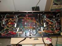
Back to OP: Nice wiring job, how does it sound?
- Status
- This old topic is closed. If you want to reopen this topic, contact a moderator using the "Report Post" button.
- Home
- Amplifiers
- Tubes / Valves
- 6L6 / 12AX7 push-pull