I believe Michael Koster suggested a different way of measuring the anode current but I don't understand how.
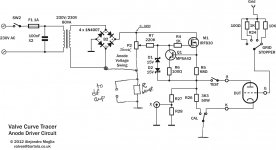
The only things that suck current from the bridge rectifier are the pot, the anode voltage divider, and the valve. Therefore, if you minimise the current taken by the pot and divider by making them 1M or greater, then you can sense the valve current by putting your sensing resistor between ground and the negative side of the bridge rectifier.
This is a common way to do it, since it no longer causes negative feedback for the valve. Of course, the voltage generated across such a resistor will be negative, but its easy enough to invert it (or invert the scope channel).
The additional current taken by the pot/divider are a source of error of course, but at least it is proportional to anode voltage, and doesn't change with valve type, unlike a cathode sensing resistor. (Actually you can eliminate the pot as an error source by returning it directly to the bridge rectifier negative terminal, rather than to ground). Just a thought.
")
Last edited:


A little more progress.
Made the patch cords, finished the adapter plates and put it some pots.
Ran out of black jacks.
Adapter wiring; Put a ferrite bead on each lead. Made a mistake on the compactron adapter, bad Pin Jack count, did 13 instead of 12. Oh well
Made the patch cords, finished the adapter plates and put it some pots.
An externally hosted image should be here but it was not working when we last tested it.
Ran out of black jacks.
An externally hosted image should be here but it was not working when we last tested it.
Adapter wiring; Put a ferrite bead on each lead. Made a mistake on the compactron adapter, bad Pin Jack count, did 13 instead of 12. Oh well
An externally hosted image should be here but it was not working when we last tested it.
The only things that suck current from the bridge rectifier are the pot, the anode voltage divider, and the valve. Therefore, if you minimise the current taken by the pot and divider by making them 1M or greater, then you can sense the valve current by putting your sensing resistor between ground and the negative side of the bridge rectifier.
This is a common way to do it, since it no longer causes negative feedback for the valve. Of course, the voltage generated across such a resistor will be negative, but its easy enough to invert it (or invert the scope channel).
The additional current taken by the pot/divider are a source of error of course, but at least it is proportional to anode voltage, and doesn't change with valve type, unlike a cathode sensing resistor. (Actually you can eliminate the pot as an error source by returning it directly to the bridge rectifier negative terminal, rather than to ground). Just a thought.
Thanks Merlin! Will try this at some point. At the moment is working fine with 1 ohm resistor and the 10x dif amp which can increase gain to x100 but probably won't touch it if it looks fine in the scope. Tried a cx301 with low anode current and image came up very neatly...
Thanks for the help
Ale
It will work with very low voltages as well -- and you don't have to float the supply which has its own issues, and you can use very low sense resistors because of the high gain of the diff amp. You can use a pair and sense current in each direction, if, for instance you wanted to do bjt's, depletion MOSFETs etc.
Pretty good over a wide range if you ask me:
An externally hosted image should be here but it was not working when we last tested it.
Very Good. Ordered one op amp to do some tests! Thanks
It will work with very low voltages as well -- and you don't have to float the supply which has its own issues, and you can use very low sense resistors because of the high gain of the diff amp. You can use a pair and sense current in each direction, if, for instance you wanted to do bjt's, depletion MOSFETs etc.
Pretty good over a wide range if you ask me:
An externally hosted image should be here but it was not working when we last tested it.
OK, it looks good down to about 8 volts, which will not be much of a limitation for plate or G2 measurement.
Also would be limited to <500V due to the P-cascode.
I would still need more than one R1 because it would not be feasable to do 1mA to 1A current measurement by switching R3 values only.
At the end of the day I think I'm going to stick with the floating supply and return side measurement for simplicity, but these do look useful in spite of the limitations and extra complexity.
Hi Merlin,The only things that suck current from the bridge rectifier are the pot, the anode voltage divider, and the valve. Therefore, if you minimise the current taken by the pot and divider by making them 1M or greater, then you can sense the valve current by putting your sensing resistor between ground and the negative side of the bridge rectifier.
This is a common way to do it, since it no longer causes negative feedback for the valve. Of course, the voltage generated across such a resistor will be negative, but its easy enough to invert it (or invert the scope channel).
The additional current taken by the pot/divider are a source of error of course, but at least it is proportional to anode voltage, and doesn't change with valve type, unlike a cathode sensing resistor. (Actually you can eliminate the pot as an error source by returning it directly to the bridge rectifier negative terminal, rather than to ground). Just a thought.
Let me check if I got it right. So if I ground the cathode and then return the pot to the rectifier bridge and the sense resistor is between the bridge return and ground I could reuse my differential amplifier to measure the anode current? In this case I can easily make rsense to be 100 ohms?
See attached
Thanks!!
Attachments
Work in progress
Very close to competion.
Very close to competion.
An externally hosted image should be here but it was not working when we last tested it.
It is working!
I am glad it did not blow up on me.
I did notice a few things though. The patch cords are a source of oscillation, especially the one going to the plate. If I twist the wire i can get it to clean up. Will a shielded cable fix this? Ferrite beads?
There is also a slight hash, not visible in pictures (taking picture from analog storage oscilloscope). I need to trace this to see where it is coming from. Is it possible to have too many ferrite beads (first time using them)?
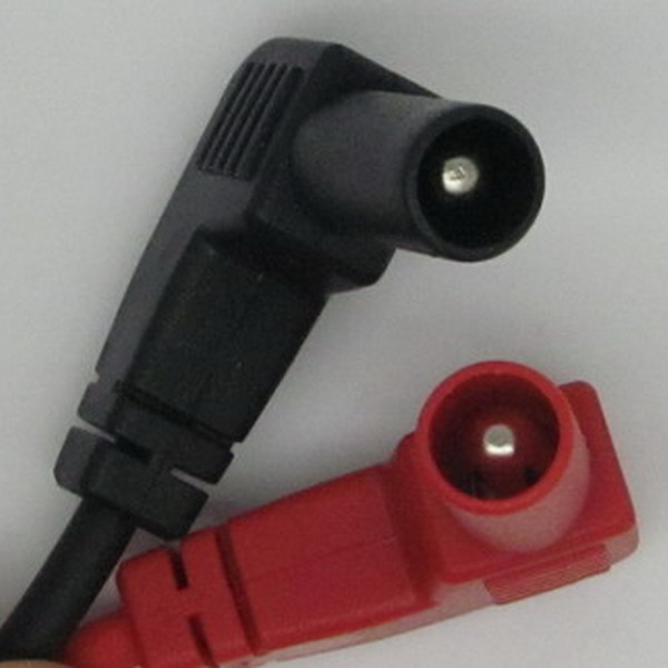
The patch cords are dangerous anyway. The hot end should be a protected female.
You may be getting some hash from the diode switching, you may get it from some oscillation as the voltage on the MOSFET is pulled down.
The only exposed points are the test points and my plan is to put some type of hood over the pins. What is a protected female jack? I can't find anyting that mount under the chassis with some type of hook to attache to probes to.
My Plate drive is very simple, same as the Tek 570.
Variac>Transformer>Full Wave Rectifier>Series Resistor>Plate. I can try with some caps accross the diodes.
Thanks
Alfredo
I rigged the connection from the tube sockets with mini-banana plugs -- these plug into the anode/grid female jacks. It's just something I've been doing since my ham radio days.
Here's the Pomona "sheathed" female: http://www.pomonaelectronics.com/pdf/D72912_01_24_06.pdf
Here's the Pomona "sheathed" female: http://www.pomonaelectronics.com/pdf/D72912_01_24_06.pdf
I rigged the connection from the tube sockets with mini-banana plugs -- these plug into the anode/grid female jacks. It's just something I've been doing since my ham radio days.
Here's the Pomona "sheathed" female: http://www.pomonaelectronics.com/pdf/D72912_01_24_06.pdf
Not sure I follow, these are very similar to the ones I am using.
The patch cord is made from cut up voltmeter leads. Male Plug and female Jack mate very solidly. I thought you were talking about the X and Y test pins.
Alfredo

Not quite the same, the protected plug and jack look like these:
Jaz
An externally hosted image should be here but it was not working when we last tested it.
Jaz
Ahh!, yes. Makes sense. However, I still have the exposed pins where I connect the probes to. These have to be taken care of first. I will do a search to see if I find something I can purchase.
I put some .01 1KV caps across the 1n4007's but they where clicking. Once I removed the caps the weirdest thing happened, the hash went away. Wonder if it was just a cold solder.
I mentioned that I was using an analog storage scope to capture he curves. It is a HP 1223a in pretty good shape. Paid 40 dollars, I thing it was worth it as it is very easy to take pictures of the curves without having any refresh issues.
Now I need to put in the finishing touches. Need to install the voltmeters, one for the heater voltage and another for the external screen voltage. I have some but they are meant for a smaller square opening. I would need to fabricate an adapter plate or purchase some new ones.
For the lettering I will give inkjet decals a shot, my handwriting wont cut it. Also need to fabricate new sides. I had to add some spacers between the top and the bottom to make everything fit. The original sides are too short now. I will fabricate new sides and front from MDF and paint the same hammer green as the socket adapters.
Cant wait to finish to do something else.... Next is a 6528 PP amp
Alfredo
With the hp 1223a i can cheat a little. Grid to ground. One screen voltage at the time, saved into the storage memory.
An externally hosted image should be here but it was not working when we last tested it.
6080 dual power triode
More testing today....
Video showing the matching feature of the curve tracer on the RCA 6080. The 6080 was the first one that I pulled from my batch of NOS tubes, all are RCA. I was very surprised that both sections are spot on.
I checked this feature with a bunch of used 12AT7 and only two out of 7 were close enough, most were way off.
More testing today....
An externally hosted image should be here but it was not working when we last tested it.
Video showing the matching feature of the curve tracer on the RCA 6080. The 6080 was the first one that I pulled from my batch of NOS tubes, all are RCA. I was very surprised that both sections are spot on.
I checked this feature with a bunch of used 12AT7 and only two out of 7 were close enough, most were way off.
one more...
A trioded PL-36. On this one I tried 2 captures on the storage oscilloscope to extend the grid steps past -60. BTW, the plate voltage is way past what the datasheet specifies. Datasheet specifies 250V max.
A trioded PL-36. On this one I tried 2 captures on the storage oscilloscope to extend the grid steps past -60. BTW, the plate voltage is way past what the datasheet specifies. Datasheet specifies 250V max.
An externally hosted image should be here but it was not working when we last tested it.
- Status
- This old topic is closed. If you want to reopen this topic, contact a moderator using the "Report Post" button.
- Home
- Design & Build
- Equipment & Tools
- DIY Curve Tracer