Something like this you suggest?
An externally hosted image should be here but it was not working when we last tested it.
Yes, hope it works.
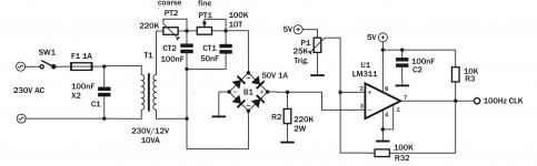
Wouldn't be safer to add a resistor between +5V rail and the bridge to limit dc current flow?
Thanks
Ale
I think that during normal operating conditions the only current drained from the bridge is via the 220k to ground. This current is much less than the 25k you already have from 5 to ground at the other input of the opamp. The current thru the 220k should be roughly similar(gestimate) as if you used a 12v transformer. Is the concern the 5V supply? That one will have many more ways to short out, maybe the current protection should be on the supply itself.
Alfredo
Alfredo
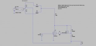
Ale, I am a bit confused as to how the circuit is working now. It seems you have two phase correction circuits. What does the 25K pot do? When you say it is all the way to one side. Are you setting the reference to the non inverting input to 5V or to 0V? When you move the 25K pot does it change the duty cycle of the 100hz clock out?
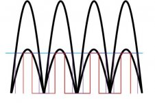
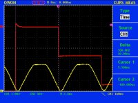
I think the comparator may be working as the picture attached. The pll and subsequent timing circuit is edge triggered. There is a large difference (picture not to scale, just as visual reference) in phase between the derived clock from a larger sine wave than a smaller one.
Alfredo
I think the comparator may be working as the picture attached. The pll and subsequent timing circuit is edge triggered. There is a large difference (picture not to scale, just as visual reference) in phase between the derived clock from a larger sine wave than a smaller one.
Alfredo
Attachments
Last edited:
Very strange indeed.
Is the winding truly isolated? No common center tap. If you temporarily hook the 12V back, does it work?I stole one 6V winding of my 6V+6V for one of the LCD meters as need to be floating.
Very strange indeed.
Is the winding truly isolated? No common center tap. If you temporarily hook the 12V back, does it work?
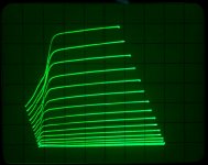
Well, I turned out that the transformer had a leak. Replaced it with another 6V+6V I had at hand and got it working again. Tried all combinations as discussed, but got stable clock signal out of the PLL with the original circuit.
In order to solve the sync adjustment issue, I added an additional RC stage to the existing one. With the original 100K/50nF I managed to get only about 3ms of phase delay which wasn't sufficient to adjust the image sync for a crystal clear set of curves.
Drawback of adding the 220K pot / 100nF RC stage for coarse adjustment is that this added additional signal drop which reduced sync window. So ended up reverting to 12V winding.
I tried many times to switch off and on the tester to see how frequently I needed to adjust the sync. And sadly it needs some minor tweaking here and there once in a while. I guess this circuit and PLL design needs improvement
Any suggestions to tweak RCRC stage? What can I do to maintain the phase shift required without dropping the 50Hz signal too much?
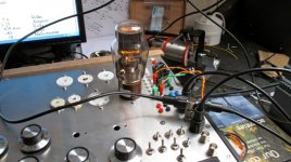
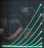
Attached are some pictures. Traced a nice 10Y and CX301a...
Cheers,
Ale
Attachments
Well, I turned out that the transformer had a leak.
I am glad you found the problem. I also have to fine tune the clock phase for the cleanest curves, don't mind doing it, it is very quick.
Alfredo
I may have missed a post here or there,
but how would you go about plotting curves for Ultralinear operation,
for say 6L6GC @ 500v or 6BG6A @ 700v?
also UL (or any) curves for an 814 would be on my wishlist.
Would you need a sample tube?
Hi Nazaroo,
I have a few 6l6GC, I can try doing the UL curves for it. What % on your transformer? When you say 500V, do you mean no plate current at 500V or Plate voltage to 1000V? I think my plate drive can only go to 750V peak. The setup to do it manually is here http://www.diyaudio.com/forums/tubes-valves/158327-help-setup-trace-ul-curves.html. I think some of the datasheets have the UL curves.
I don't have a 814 or 6BG6A. Could trace it for you if you send me one. PM me if you want to.
Alfredo
I am glad you found the problem. I also have to fine tune the clock phase for the cleanest curves, don't mind doing it, it is very quick.
Alfredo
Hi Alfredo,
Thanks. I still feel I can improve the circuit.
I generally need to resync when changing type of valves under test. Some are more challenging than others.
Do you experience the same?
Breadboard seemed to be perform better. Added a lot of ferrite beads in anode and grid cables. And also these are twisted pairs with ground signal.
Cheers
Ale
Hi Nazaroo,
I have a few 6l6GC, I can try doing the UL curves for it. What % on your transformer?
Hi avincenty:
I have a 'standard' UL transformer (100w) and
I think 18/40 impedanceZ/windings for the UL taps.
When you say 500V, do you mean no plate current at 500V or Plate voltage to 1000V? I think my plate drive can only go to 750V peak.
I meant plate voltage (and so the screen would also be 500v dc).
You should be able to push a 6L6GC tube to 500-550 v on the plate safely.
The setup to do it manually is here http://www.diyaudio.com/forums/tubes-valves/158327-help-setup-trace-ul-curves.html. I think some of the datasheets have the UL curves.
The datasheets for UL curves have usually been artificially constructed by flipping over a triode-curve.
Not measured.
Ok I'll figure out the PM thing next.I don't have a 814 or 6BG6A. Could trace it for you if you send me one. PM me if you want to.
Alfredo
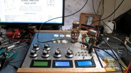
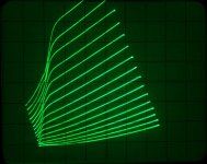
Up and running
Fixed some additional outstanding things and now is running properly.
Attached is a nice 10Y plot.
Re sync adjustment, the PLL drifts very slowly. After 15-30min of operation, the phase delay available on the RCRC stage is not sufficient and retracing goes back again to the end of the curves (i.e. right of the scope). After a while I can resync it.
Anyone expert in the 4046 PLL can please suggest a way of improving the stability of the locking if possible?
Other than that, it works like a charm!
I have spotted a couple of noisy / worn out 46 and CX-245 , so its quite useful tool to look at this in addition to the linearity of curves, etc.
Cheers,
Ale
Fixed some additional outstanding things and now is running properly.
Attached is a nice 10Y plot.
Re sync adjustment, the PLL drifts very slowly. After 15-30min of operation, the phase delay available on the RCRC stage is not sufficient and retracing goes back again to the end of the curves (i.e. right of the scope). After a while I can resync it.
Anyone expert in the 4046 PLL can please suggest a way of improving the stability of the locking if possible?
Other than that, it works like a charm!
I have spotted a couple of noisy / worn out 46 and CX-245
, so its quite useful tool to look at this in addition to the linearity of curves, etc.Cheers,
Ale
Attachments
HI Ale,
My clock is very stable. It has a 50/50 chance of locking to the next cycle in which case I see a very small glitch on my last step transition. Redoing the phase adjustment gets rid of it. Probably doing some type of reset based on the 50hz signal leading edge (60 in my case) may do it so that the phase adjustment can remain fixed. It is adding more to the circuit. I am ok with the 50/50 and adjusting phase as necessary. My clock is stable though, no drift.
I made a new front plate to hide the original extra holes and to fit the Panel Meters. I also added a switch that toggles between sensing the current with a 10ohm vs a 100ohm resistor. My next step is to reprint labels for the switches and pots.
I discovered something else. In one of my previous posts I had mentioned a high frequency hash that was getting in. The hash was visible directly by monitoring the ground with everything turned off. I suddenly remembered that I have a Powerline Ethernet device that I use for my Squeezbox Touch. I turned it off and and presto, the hash is gone. Also, it picks up the microwave oven Luckily we only use it to reheat stuff. Anyone knows of how to effectively and cheaply filter that stuff out from the powerline?
My clock is very stable. It has a 50/50 chance of locking to the next cycle in which case I see a very small glitch on my last step transition. Redoing the phase adjustment gets rid of it. Probably doing some type of reset based on the 50hz signal leading edge (60 in my case) may do it so that the phase adjustment can remain fixed. It is adding more to the circuit. I am ok with the 50/50 and adjusting phase as necessary. My clock is stable though, no drift.
I made a new front plate to hide the original extra holes and to fit the Panel Meters. I also added a switch that toggles between sensing the current with a 10ohm vs a 100ohm resistor. My next step is to reprint labels for the switches and pots.
An externally hosted image should be here but it was not working when we last tested it.
I discovered something else. In one of my previous posts I had mentioned a high frequency hash that was getting in. The hash was visible directly by monitoring the ground with everything turned off. I suddenly remembered that I have a Powerline Ethernet device that I use for my Squeezbox Touch. I turned it off and and presto, the hash is gone. Also, it picks up the microwave oven
Luckily we only use it to reheat stuff. Anyone knows of how to effectively and cheaply filter that stuff out from the powerline?Use a common mode choke and a couple of X and Y rated caps.
Typical common mode filter.
I got some standard EMI filters to see if that will help. Need to hook it up and reconnect the Power Ethernet network..
Thanks for the suggestion.
Link to UL thread
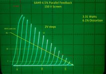
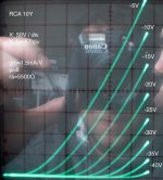
Here is a link to another thread I have been collaborating on to trace UL curves. I was able to follow some of the suggestions and use a Mosfet along with a dividing network to simulate the UL behavior. These curves show Plate Voltage vs (Plate+Screen) current. I am posting some of the pictures here as I feel they are relevant to the whole curve tracer topic.
Here is a link to another thread I have been collaborating on to trace UL curves. I was able to follow some of the suggestions and use a Mosfet along with a dividing network to simulate the UL behavior. These curves show Plate Voltage vs (Plate+Screen) current. I am posting some of the pictures here as I feel they are relevant to the whole curve tracer topic.
Attachments
- Status
- This old topic is closed. If you want to reopen this topic, contact a moderator using the "Report Post" button.
- Home
- Design & Build
- Equipment & Tools
- DIY Curve Tracer