Hi everybody.
I wanted to build this phono stage as a present for a friend:
http://www.vinylsa.co.za/pdf/A Simple Phono Preamp Using A Pair Of 6DJ8_ECC88 Tubes.pdf
I have not made any changes to the circuit itself, though I'm not using the
power supply described in the paper. I decided to use a really regulated one.
Now I've run into the following problem:
With no record player connected to the input the circuit is reasonably quiet
and hum free.
But as soon as I connect a record player to the input I get a horrible hum.
I have made some pics of my scope connected to the plate of the second
triode.
The first pic shows what's going on there without a source connected.
The next picture show what happens when a 47k resistor is connected
across the input:
The scope was set to X: 10mV/Div Y: 5ms/Div
So the trace in the first pic shows about 5mVpp and the second one
about 30mVpp.
What I really don't get now is why this happens as soon as the input is
"loaded" with 47k (equivalent of cartridge).
I reckon it's got something to do with faulty grounding but I have not been
able to find my error.
Maybe someone could point me in the right direction and give me a push?
David
I wanted to build this phono stage as a present for a friend:
http://www.vinylsa.co.za/pdf/A Simple Phono Preamp Using A Pair Of 6DJ8_ECC88 Tubes.pdf
I have not made any changes to the circuit itself, though I'm not using the
power supply described in the paper. I decided to use a really regulated one.
Now I've run into the following problem:
With no record player connected to the input the circuit is reasonably quiet
and hum free.
But as soon as I connect a record player to the input I get a horrible hum.
I have made some pics of my scope connected to the plate of the second
triode.
The first pic shows what's going on there without a source connected.
An externally hosted image should be here but it was not working when we last tested it.
The next picture show what happens when a 47k resistor is connected
across the input:
An externally hosted image should be here but it was not working when we last tested it.
The scope was set to X: 10mV/Div Y: 5ms/Div
So the trace in the first pic shows about 5mVpp and the second one
about 30mVpp.
What I really don't get now is why this happens as soon as the input is
"loaded" with 47k (equivalent of cartridge).
I reckon it's got something to do with faulty grounding but I have not been
able to find my error.
Maybe someone could point me in the right direction and give me a push?
David
Maybe someone could point me in the right direction and give me a push?
The circuit is pretty straightforward and you have an oscilloscope handy. Measure PSU ripple (and let us know which version of PSU you chose, there appear to be two versions presented in that PDF), then observe anode and cathode voltages with 47K shunt across input - does it appear that PSU noise is injected at any of those four points ?
Remember: high voltage ! You only have to observe AC waveforms.
What is your actual grounding scheme (star ground or not) ?
Where do you take your ground from for each section ?
It does happen on both cannels. Circuit ground is not connected to chassis earth.
Thanks for your replies guys.
I'm using star grounding scheme, central ground point is the negative side of the power supply.
I had time to think about it now and that might actually be my mistake.
My working theory at this moment is as follows:
1. The ripple that is visible on the scope looks like some mishmash of 50/100Hz frequencies.
2. I think I connected the RCA jack's ground directly to my star point. Not the same
wire that goes to the circuit board. Obviously that would result in a different potential
on the ground wire leading to the RCA jacks. When I connect this point to the amp's
input via 47k (or the cartridge) I inject the noisy stuff from the ground wire into the
circuit. Result: appalling hum.
I'll have to check that out tonight.
If the above turns out to be the problem I'll have to rethink my grounding system.
Maybe it would be better to put the central ground away from PSU to a point closer
to the circuit board? So all grounds would be closer to the ground potential at the
most sensitive point in the whole amp.
I would be interested in what you guys think about grounding.
The PSU is OK, there is no oscillation and only a little noise, no hum measurable.
I decided to use this circuit (sorry, only German):
Der Treffpunkt für Elektronik, Mikrocontroller, Röhre, Forum, Platinen, Schaltungen, Onlineshop
It's rather straight forward. But it has real regulation as opposed to the PSU described
in the paper. I prefer that. Additional to the regulator I put in a chain of C-R-C
filters with a calculated ripple rejection of about 90dB.
This is what it looks like on the scope:
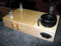
Another thing might be inductive coupling from the mains trannies. I couldn't
use separate enclosures, so they are closer to the circuitry than I would usually
prefer. I use copper clad circuit board as a shield between PSU and signal
compartments. I might actually stick the whole circuit board (excluding tubes) into
a box made from the stuff. I have had very good results doing that before.
Well, we'll see...
David
Thanks for your replies guys.
I'm using star grounding scheme, central ground point is the negative side of the power supply.
I had time to think about it now and that might actually be my mistake.
My working theory at this moment is as follows:
1. The ripple that is visible on the scope looks like some mishmash of 50/100Hz frequencies.
2. I think I connected the RCA jack's ground directly to my star point. Not the same
wire that goes to the circuit board. Obviously that would result in a different potential
on the ground wire leading to the RCA jacks. When I connect this point to the amp's
input via 47k (or the cartridge) I inject the noisy stuff from the ground wire into the
circuit. Result: appalling hum.
I'll have to check that out tonight.
If the above turns out to be the problem I'll have to rethink my grounding system.
Maybe it would be better to put the central ground away from PSU to a point closer
to the circuit board? So all grounds would be closer to the ground potential at the
most sensitive point in the whole amp.
I would be interested in what you guys think about grounding.
The PSU is OK, there is no oscillation and only a little noise, no hum measurable.
I decided to use this circuit (sorry, only German):
Der Treffpunkt für Elektronik, Mikrocontroller, Röhre, Forum, Platinen, Schaltungen, Onlineshop
It's rather straight forward. But it has real regulation as opposed to the PSU described
in the paper. I prefer that. Additional to the regulator I put in a chain of C-R-C
filters with a calculated ripple rejection of about 90dB.
This is what it looks like on the scope:
An externally hosted image should be here but it was not working when we last tested it.
Another thing might be inductive coupling from the mains trannies. I couldn't
use separate enclosures, so they are closer to the circuitry than I would usually
prefer. I use copper clad circuit board as a shield between PSU and signal
compartments. I might actually stick the whole circuit board (excluding tubes) into
a box made from the stuff. I have had very good results doing that before.
Well, we'll see...
David
Your star ground needs to be connected to the chassis of the pre-amp at one point otherwise differences in potential between the chassis and your circuit ground will be electrostatically coupled into the circuitry.
47K is the "recommended" cartridge load impedance, most MM cartridges have source impedances of considerably less than 1K, a 220 - 560 ohm resistor is a reasonable approximation for most MM types. High output MC are generally well under 50 ohms, and low output MC from a high of maybe 15 ohms to a low of 3 ohms or so.
Any noise level over a hundred uVrms (not mV!) at the output of a phono pre-amplifier should be a cause for major concern if you want anything approaching a reasonable SNR. (Assuming ~ 40dB of gain referenced to 1kHz)
Last edited:
Ground the turntable properly!
Since the preamp is reasonably quiet on it's own, and the hum comes after you've hooked up the turntable, obviously there is nothing wrong with your pre. It is absolutely crucial that the turntable is grounded to the pre with a seperate ground wire. Usually the turntable has a dedicated wire for this, which is intended to be connected to the pre.
If you have hooked up this ground wire, there is still something wrong in front of your pre, and not the pre itself. Look at how your cartridge is hooked up and double check it's correct, also check the grounding wire is actually grounding the turntable and not just floating.
Thanks for your replies so far.
I've rewired the thing yesterday. I moved the star ground point from the PSU to the
circuit board. This has reduced hum quite drastically, I'm still not 100% satisfied though.
The problem really seems to have been the different ground wires running to the RCA
jacks and the circuit respectively.
I still get a little hum on the output of the pre-amp, I measured about 2mVrms.
This is OK for listening through speakers but still too much for headphone use.
Noise on the other hand is great, meaning there is virtually none.
The hum has nothing to do with turntables, I have tried two different ones and they
both work perfectly on two others of my DIY RIAA amps. The ground wire is hooked up
correctly.
So there is still some room for tweaking. I just have to figure out where.
David
I've used DC heating from the get go, it's a standard LM317 job with 2x4700uf caps.
I wouldn't dream of introducing AC through filaments and wiring. The neg. side of filament PSU is tied to ground too.
Arnulf what do you mean by CT?
David
EDIT:
I might try to separate signal and power ground points, next. I still think I've got some nasty grounding problem.
I wouldn't dream of introducing AC through filaments and wiring. The neg. side of filament PSU is tied to ground too.
Arnulf what do you mean by CT?
David
EDIT:
I might try to separate signal and power ground points, next. I still think I've got some nasty grounding problem.
Last edited:
I've used DC heating from the get go, it's a standard LM317 job with 2x4700uf caps.
I wouldn't dream of introducing AC through filaments and wiring. The neg. side of filament PSU is tied to ground too.
Arnulf what do you mean by CT?
Oh ... you should have pointed this out before, schematic you posted shows AC supply.
CT = center tap, shown in said schematic.
Ah, I said as much in the opening post... but never mind.
This thing is doing my head in. I can't get it silent. Up until the grid of the second
triode everything seems fine. The hum seems to be added by the second tube.
B+ is clean, no hum to be seen, only a bit of noise.
Now what do I do? I'm a bit lost here now.
So I've made some screenshots of the scope again.
Settings are:
upper trace X: 5mV/div Y: 2ms, measured with 1:1 probe
lower trace X: 5mV/div Y: 2ms, measured with 1:10 probe
The lower trace in poth pics show the B+ directly at the plate resistor of the 2nd
triode stage.
The upper trace in this pic shows whats going on at the 2nd triodes grid:
This pic shows whats coming out of this triodes plate:
Any suggestions?
David
This thing is doing my head in. I can't get it silent. Up until the grid of the second
triode everything seems fine. The hum seems to be added by the second tube.
B+ is clean, no hum to be seen, only a bit of noise.
Now what do I do? I'm a bit lost here now.
So I've made some screenshots of the scope again.
Settings are:
upper trace X: 5mV/div Y: 2ms, measured with 1:1 probe
lower trace X: 5mV/div Y: 2ms, measured with 1:10 probe
The lower trace in poth pics show the B+ directly at the plate resistor of the 2nd
triode stage.
The upper trace in this pic shows whats going on at the 2nd triodes grid:
An externally hosted image should be here but it was not working when we last tested it.
This pic shows whats coming out of this triodes plate:
An externally hosted image should be here but it was not working when we last tested it.
Any suggestions?
David
Ah, I said as much in the opening post... but never mind.
Ah, this is why we ask everybody to post actual schematic of circuit in question when asking for advice regarding problems they are experiencing
")
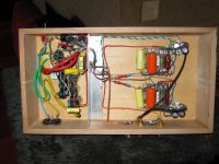
Please elaborate on whether that is grid to cathode voltage in your photo or not and post a high resolution photo showing your circuit, especially the part around 2nd stage grid (including R8), perhaps some wiring errors will be evident from the photo.
- Status
- This old topic is closed. If you want to reopen this topic, contact a moderator using the "Report Post" button.
- Home
- Amplifiers
- Tubes / Valves
- Need some help with RIAA Preamp