Thanks for all your help and input. Great forum!
Yes, I know veroboard and wires are not the best way of building things like this, but it usually works just fine. I've not etched a board in years - to be honest I hate it. All that mess...
I'll try what kevinkr suggested and put some grid/anode resistors directly to the sockets.
How would one use twisted cables exactly? The signal carrying wire is clear, but what about the grounded wire? Do you just ground it on one side or on both?
Useage of twisted pairs seems to be more common elsewhere, I wouldn't even know where to get twisted wires in Germany.
Several people have now remarked that it would be a good idea to let the filament circuit float on a bias. Can someone explain to me how that's done? I'm not quite sure how that would work and what would be the benefit. A small example might clarify things.
David
Elevated heater supply: set up a voltage divider on B+, make it draw a small amount of current so the resistors don't overheat. It should be within heater to cathode safety ratings for chosen tube, in realuity something along the liens of 50V is just fine. Put a couple hundred uF or thereabouts capacitor there. Reference one end of heater supply to this point.
Why ? Hot heater inside cathode "sleeve" can act as a vacuum diode if it is at same (or lower) potential than cathode. Whatever noise there might be in supply could couple to cathode.
Does this happen with DC supply ? It shouldn't, but you're making a phono stage so every bit of noise can be a bit too much.
Where to get twisted pair wiring ? UTP (computer network) cables are loaded with it, just rip the outside insulation open and you've got 4 pairs") They are usually used for balanced signals. For high voltage (which could be the source of your poblems) you should just twist existing (higher voltage capable) cables.
They are usually used for balanced signals. For high voltage (which could be the source of your poblems) you should just twist existing (higher voltage capable) cables.
Definitely put grid stoppers (shown in your schematic) directly onto grid pins ! This is precisely why photos help so much in debugging problems. You've got what, 10 cm of cables between them and grids at least.
Why ? Hot heater inside cathode "sleeve" can act as a vacuum diode if it is at same (or lower) potential than cathode. Whatever noise there might be in supply could couple to cathode.
Does this happen with DC supply ? It shouldn't, but you're making a phono stage so every bit of noise can be a bit too much.
Where to get twisted pair wiring ? UTP (computer network) cables are loaded with it, just rip the outside insulation open and you've got 4 pairs
They are usually used for balanced signals. For high voltage (which could be the source of your poblems) you should just twist existing (higher voltage capable) cables.Definitely put grid stoppers (shown in your schematic) directly onto grid pins ! This is precisely why photos help so much in debugging problems. You've got what, 10 cm of cables between them and grids at least.
Elevated heater supply: set up a voltage divider on B+, make it draw a small amount of current so the resistors don't overheat. It should be within heater to cathode safety ratings for chosen tube, in realuity something along the liens of 50V is just fine. Put a couple hundred uF or thereabouts capacitor there. Reference one end of heater supply to this point.
This reference point substitutes for using the common star as the heater reference. So, instead of making the connection I have shown for the heater loop, just connect the heater loop reference to the voltage divider.
With a 300V supply, for example, you could use a divider consisting of 130k and 20k resistors, with the 20k on the common end. That would pass 2mA of current, and the voltage at the center of the divider would be 40V. Then connect a capacitor of at least 10uf from the center of the divider to common (larger is even better).
These values are just examples. You can use what you have on hand. You want to pass around 1-2mA through the divider, voltage should be 20-50V when your cathodes are near the common potential, and the Fc of the filter that is formed by the bottom resistor and cap, should be less than about 1Hz.
Don't worry too much about the twisted pair comment. I use them where convenient, i.e., where the signal wire and common connections are fairly close together at both ends. If the common connection is not right next to the signal connection, I run the wires twisted to the signal connection and continue the common on to its connection. If the signal and common are widely separated, shielded wire might work better.
Sheldon
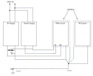
Note that to float the heaters you must have a heater power and return that does not share the ground as shown in your drawing. In effect you would have 4 wires from the PSU to the phono preamplifier - they are : B+, GND, HTR1 and HTR2.
Using dc for the heaters and biasing the whole heater circuit to roughly +50V should help. Note that the heater dc must be ripple free via either regulation or very good filtering. Some ripple can be much worse in terms of electro-static coupling into nearby wiring and via the filament/cathode capacitance and diode action between the two than with regular ac due to the high dv/dt of the ripple waveform as compared to a sinewave.
Using dc for the heaters and biasing the whole heater circuit to roughly +50V should help. Note that the heater dc must be ripple free via either regulation or very good filtering. Some ripple can be much worse in terms of electro-static coupling into nearby wiring and via the filament/cathode capacitance and diode action between the two than with regular ac due to the high dv/dt of the ripple waveform as compared to a sinewave.
Note that to float the heaters you must have a heater power and return that does not share the ground as shown in your drawing. In effect you would have 4 wires from the PSU to the phono preamplifier - they are : B+, GND, HTR1 and HTR2.
I tried to describe that in my previous post. Picture is better (if a separate chassis is used for the power supply, 5th wire is needed to connect both chassis to earth).
Attachments
After tinkering with the bloody circuit for another evening I've finally had enough.
I realised that without major changes I couldn't get it to be quiet.
So major changes I made. I ripped the whole circuit apart and abandoned the circuit
board alltogether in favour of the classical aproach using "solder tag strips" (what do
you call them in English?).
I rebuilt the circuit using them and it works perfectly. There is no noise and no hum
until i turn the volume knob way up.
Now I only have to finish the enclosure and the present is ready.
Thanks for all your help, especially regarding proper grounding. That has helped me with the second version, too.
David
An externally hosted image should be here but it was not working when we last tested it.
An externally hosted image should be here but it was not working when we last tested it.
Hallo,
I aim for 250 Volts B+. Here are some pics of my RIAA.
Kind regards from Holland
Ben
This is off topic, but what design is your KT88/6550 amplifier. Do you have a schematic or link?
A KT88 PP amp is my next project.
Thanks
Glenn
- Status
- This old topic is closed. If you want to reopen this topic, contact a moderator using the "Report Post" button.
- Home
- Amplifiers
- Tubes / Valves
- Need some help with RIAA Preamp