I'm trying to make some sense out of my Sweet Peach SE amplifier, being a tube noob its coming along very slowly. I have a schematic off of the manufacturers web site but the values are almost impossible to read so I metered all the resistors and some of the caps to flesh out the schematic. I have a couple of burning questions I'm hoping someone can help me with. I see a 3k resistor between v1 (6n3p) and v2 (6n1p) as well as a 3k between 6n1p and the GU50, what purpose does this resistor serve? Is it there to artificialy lower the value of the coupling Caps (all are .1uf MKP's)? I'm not certain of why there are 47k resistors upstream of the V1, V2 anodes just there to knock the B+ down? Finally the 6n1p has a 1k cathode resistor which seems to be high, can I install ~200 ohm cathode resistor without changing any of the other components, was also thinking of substituting a 6n6p in place of the 6n1p (less gain, pleasant sound) but it also likes more current and normally uses about 200 ohm cathode resistor, can this be done without burning the house down?
Attachments
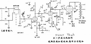
The 47 K anode resistors are there as anode loads to develope the output voltage. As the grid voltage changes, the current through the tube changes. If you tied the anodes to B+ there would be no changing voltage output that could be coupled throgh the capacitors to the next stage. The changing current through the resistors produces a corrrosponding changing voltage which it the amplified signal.
No, you can't simply change the 1K resistor to a 200 Ohm resistor without upsetting the bias point of the tube.
On the other hand, if you change to 6N6P it won't sound as good as it will if you do change the cathode resistor from 1K to a lower value (I don't know if 200 Ohm is an optimum value or not).
I suggest you do some reading on tube theory to get a good basic understanding before making any changes to the circuit.
This is a good place to start:
http://www.diyaudio.com/forums/tubes-valves/38278-line-tube-learning-newbies.html
along with this for safety:
http://www.diyaudio.com/forums/tubes-valves/30172-safety-practices-general-ultra-high-voltage.html
If you have any 6n6p you should be able to plug it right in without changing anything for a start. The 6n6 will draw a little more heater current, but should not matter that much since we only have one driver tube.
Ideally you might want to run it at a little higher current than the present 5mA which would require lower value cathode and anode resistors. This will draw more current from the B+ so you should check if you have any to spare. If the PT is not running very hot, some extra current may be OK, and you could reduce cathode and anode resistors for a hotter operating point, say 12mA?
Some care is required when choosing operating point for the driver since it must deliver 130V peak-to-peak for the GU50.
The reduction in gain will not be immediately apparent unless the global feedback is adjusted.
The gain seem to be on the high side in this amp, about 60x from input to speakers - with the global feedback. The gain could be reduced to about half by removing the cathode bypass on the input tube. The feedback may then have to be adjusted again - if you feel it is needed.
Svein
Thank you all very much for the feedback, I have actually done a significant amount of reading over the past 2 years or so on basic electronics and more recently on valves I just need to see these principles in action, that and sometimes you just want answers! I have had the 6n6p's sitting in the closet waiting for a project, a cursory look at the data sheet suggests they can be used in this amp so I popped one in for a while and enjoyed the sound quality. My power trafo is nearly stone cold so I thought I should have some current to spare for the 6n6p.
I would say the stock chineese 6n1 is probably the weakest link, kinda harsh and shouty, the russian 6n1p-ev is significantly better sounding. The 6n6p sounds different, cybals and drums are more transparent and silky while the 6n1p has more kick (very subjective, I know)but this is with the stock circuit. The GU50's drop right in but all of mine did a lot of popping for the first minute or so of operation, they have worked fine since.
S.Spielbergo -> Previously I have used russian 6n1p and they didn't let me down. Beautiful to look at and good sound.
I will continue to follow this thread even more when my amp arrives. Guess I'll order some tubes in a week or two just to make sure I already have them when the amp arrives.
I will continue to follow this thread even more when my amp arrives. Guess I'll order some tubes in a week or two just to make sure I already have them when the amp arrives.
Last edited:
I'm still trying to figure out how the 6n1p is being used at such low B+ voltages. I meter 200V above the 47k plate resistor and about 130v beneath it at the valve socket. I see that at 130v the 6n1p needs to idle at a super low current and the load line spans the most nonlinear portion of the curves at the very bottom. The 6n6p would be much happier with lower B+ voltages and seems to have better curves for this application.
I'm still trying to figure out how the 6n1p is being used at such low B+ voltages. I meter 200V above the 47k plate resistor and about 130v beneath it at the valve socket . . .
You are right, with 200V for the B+ supply to the driver tubes they will be starved.
From the pictures you posted earlier in: http://www.diyaudio.com/forums/tubes-valves/159686-any-pretty-good-bad-chinese-amps-6.html
I see a RC stage from the 400V for additional smoothing of the supply to the driver board. The resistor (located on the edge of the PS board) looks to me as if it might be 2k or 2.7K. If it should happen to be 27K instead, it will drop the voltage to around 200V, which in my opinion is to low.
The estimates and suggestions I have made earlier are based on a supply voltage of 360-380V to the driver board.
Attached is a loadline for 6N1P with 380V supply and 47K anode load. It will be reasonably linear.
Imagine pushing that line down so it crosses 200V and idles at around 1.5mA and it will not perform well.
Svein
Attachments
Edit: Found it... Have been wondering what kind of tube the chinese 6n1 really is. Found no facts what so ever about it until i found a page that stated that it really is the same as the 6n1p.
The closest thing I found other than 6n1 was a chinese tube called 6n11 and that tube is supposed to be an equivalent to the 6n23p (Russian: 6Н23П)or ecc88 or 6922. Which may not be a good substitute since the allowed plate voltage is so low...
The closest thing I found other than 6n1 was a chinese tube called 6n11 and that tube is supposed to be an equivalent to the 6n23p (Russian: 6Н23П)or ecc88 or 6922. Which may not be a good substitute since the allowed plate voltage is so low...
Last edited:
That 200V measured by Spielbergo on the top of the anode resistors on the 6N1P does not make sense to me.
If the power resistor on the PS board is 2K and is dropping 400V to 200V it would have to carry 100mA, and dissipate 20W + some smoke.
I do not see any other likely source for a 200V supply.
SveinB
If the power resistor on the PS board is 2K and is dropping 400V to 200V it would have to carry 100mA, and dissipate 20W + some smoke.
I do not see any other likely source for a 200V supply.
SveinB
Yes, its a little confusing especially with such a poor schematic. There is 429v B+ on the power supply board, then you have the large resistor (2.2k) on the edge of the board that drops the voltage down to 401v, a short length of wire takes B+ to the preamp board where it encounters another resistor (47.6K) that drops voltage all the way down to 210v. I metered it with a new meter and it is the same, if I can get B+ down to 180-190v then I can use the 6n6p
I have tried to analyse the (sometimes confusing) information gathered so far, and marked up a circuit diagram with the most significant component values and voltage estimates.
The 6n1p seem to operate at about 4mA with Va=200V. The corresponds roughly to the loadline I showed in post #10on the previous page.
If you plug in a 6n6p it should come to rest at a little below 6mA and Va around 130V which should be quite OK.
I will see if I can try to suggest some alternate operating points with a little higher currents later.
SveinB.
Attachments
Last edited:
Rockmore, my entire reason for buying this amplifier was to reverse engineer it and learn more about valve amps. I count myself almost fortunate that there are some non sequiters with the driver circuit as it provides a great opportunity to learn, in fact I have learned more in the past few days than the past few months reading books on and off again between renovation projects at home. FWIW I already emailed the manufacturer about providing a legible schematic 3 weeks ago with no reply. This thing is made in China and sold QUITE cheap (nearly at a loss after shipping), I don't expect much customer support.
Svein_B, I appreciate your patience and feedback, and yes with a 6n6p in place you see 130v with the added current draw. My attempt at drawing a load line for the 6n6p at 130v yielded a negative swing that was greater than the positive swing, wouldn't this pose a problem?
Svein_B, I appreciate your patience and feedback, and yes with a 6n6p in place you see 130v with the added current draw. My attempt at drawing a load line for the 6n6p at 130v yielded a negative swing that was greater than the positive swing, wouldn't this pose a problem?
- Status
- This old topic is closed. If you want to reopen this topic, contact a moderator using the "Report Post" button.
- Home
- Amplifiers
- Tubes / Valves
- Trying to make sense of the Sweet Peach