Hi Rolf
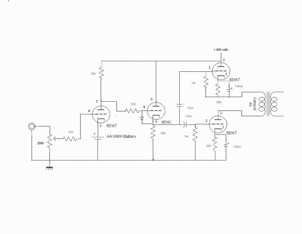
Maybe you could do something like this with the power amp.
It's the same principle as the accordian (series-connected output tubes sharing the voltage equally), but a lot simpler.
If there's a speed problem with the upper output tube, that could be corrected with a small cap across the bottom 47K resistor. Should be OK as is though.
Good luck anyway. 🙂
Cheers - Godfrey
Edit: No good for a phase-splitter though...
A cascode with feedback... Increases effective mu (stage gain) and increases effective plare resistance vs a single tube. The mu and plate resistance can be tuned by the ratio of the 2 resistors (47k) from that of the one tube (bypass upper R with a cap) to pentode-like (upper R connected to B+) but of course with a DC circuit the DC op point is also affacted.
I don't know the advantage for an output stage unless for example you want to use 6C33s in a high voltage high impedance circuit. I have found it useful in e.g. mic preamp gain stages.
Last edited:
Godfrey'
merlinb,
I know it is quite a mind stretch to see the hidden voltage amplifier that looks like a cathode follower. But what I realize now is that the two output sections, effectively, are not getting the same input signal. The top tubes "ground", the bottom of it's cathode resistor, is radically changing in voltage with the signal amplified by the bottom section. the grid needs a signal that "rides?" up and down with the cathode voltage to drive this tube properly.
What I meant was, although the top tube is not supposed to be a a cathode follower, you' have forced it to be one because of the way you are driving it. (I'm talking about this schem you posted BTW http://www.diyaudio.com/forums/atta...588714-phase-splitter-idea-accordion-6em7.jpg)
Your input signal to the top tube is ground referenced, but it's grid is referenced to the cathode as you pointed out, so the cathode will do its best to follow the grid. You need to somehow ensure the input signal is also referenced to the cathode, that is, it is generated directly between grid and cathode, not between grid and ground as you have it now. Only then will the output stage be symmetrical.

Well,
I haven't looked at this thread since my last post. I have bought some universal interstage transformers from Triode Electronics and breadboarded one channel like this. It works like a charm. When I pull either of the secondaries, the output voltage as seen on my oscilloscope drops to half. Now I know the accordion principal works.
Godfrey:
I thought of doing a cascode but I wanted to see the accordion working. That said your design is pretty cool and does not require adding two large chunks of iron to my existing amp. Since I have it all laid out on the breadboard anyway I am going to try it. Thanks.
Cheers.
Rolf.
Attachments

Excellent!It works like a charm.
 I was wondering where you'd got to.
Now for a totally OT question: How are you powering the heaters?
Reason I ask is I'm always a bit wary of stuff like cathode followers, cascodes and SRPP because datasheets always say the heater must be within X volts of the cathode.
This usually means a lot of extra hassle with floating heater supplies or separate supplies for the top and bottom tubes etc.
I've always wondered how serious the limit is i.e. how much heater-cathode current do you actually get if you go beyond the limits and is it bad for the tube?
OTOH, I see the 6EM7s you're using are quite generous (+-200V H-K allowed), so I suppose you can just bias all the heaters at +200V or so and be done with it?
Cheers - Godfrey
Last edited:
Hi Godfrey.
I am using separate heater supplies. I don't like to push the limits that close. After all they aren't making these tubes anymore. It is just one small 5 volt transformer to squeeze in.
I tried your cascode idea, but it didn't work too well. It only put out 10 volts peak to peak at the speaker leads as opposed to almost 20 for the transformer coupled accordion. Also the accordion clips normally while the cascode suddenly got very ugly. Maybe it could be tweaked to work good, But I think it will stick to the original plan.
The breadboarded Accordion sounds pretty good even though it has the wrong output transformer. A 5k load is good for a single tube, this should really have 10k. I might get 8k ones as a compromise for a bit more power.
I don't think it will ever sound as sweet as Gary Kaufman's DC 6em7 which is my first tube amp. This project is a crossbreed of that amp with the accordion idea. Maybe higher quality interstage transformers would add that final touch but also a lot more expense.
Cheers,
Rolf.
I like Don's solutions, just wish he'd find a more legible crayon.
Whats your beef against LTSpice? Even if just to draw stuff...
I gotta try that one with the P-Ch.
Whats your beef against LTSpice? Even if just to draw stuff...
I gotta try that one with the P-Ch.
Nothing against LTSpice, I probably should start using it. But it just takes me a few seconds to draw something up on paper and scan it. Usually starts out as a scribble on paper already while working on the idea.
On the P-channel Split-P splitter, R3 could be replaced with an identical P-Mosfet to form a full current mirror (drain and gate connected). R4 gets tweeked until the output gains match. I like the cathode feedback checking on the splitter accuracy in that scheme. Will have to try it out soon too. I just got some Edcor xfmrs in to build a few amps, so I will be trying out a bunch of new ideas piled up on the stack here.
On the P-channel Split-P splitter, R3 could be replaced with an identical P-Mosfet to form a full current mirror (drain and gate connected). R4 gets tweeked until the output gains match. I like the cathode feedback checking on the splitter accuracy in that scheme. Will have to try it out soon too. I just got some Edcor xfmrs in to build a few amps, so I will be trying out a bunch of new ideas piled up on the stack here.
Nothing against LTSpice, I probably should start using it. But it just takes me a few seconds to draw something up on paper and scan it. Usually starts out as a scribble on paper already while working on the idea.
On the P-channel Split-P splitter, R3 could be replaced with an identical P-Mosfet to form a full current mirror (drain and gate connected). R4 gets tweeked until the output gains match. I like the cathode feedback checking on the splitter accuracy in that scheme. Will have to try it out soon too. I just got some Edcor xfmrs in to build a few amps, so I will be trying out a bunch of new ideas piled up on the stack here.
Like this?
Sketch from my notebook sometime last week...
I have been playing with a few different inverter circuits lately. Using the second PMOS makes the DC voltage the same in the sources so you can use the same value R7 and R8. A little difference in static current is OK. Actually the DC difference is so noncritical you could probably replace Q1 with diodes.
Attachments

Last edited:
P-Splitter cascode concertina
Somewhat related ;-)
Here's another half-baked idea using a P-MOSFET cascode where the -Vgs of the MOSFET biases the tube Vgk. The input is centered between the rails, but that could be useful for some topologies. It has good voltage gain but needs 2X the supply voltage rail2rail vs. an LTP for the same output voltage.
It could be biased in other ways for use with a unipolar supply.
Michael
Attachments

"Like this?"
Yup. Can optionally return R4 to the top of R3 for additional feedback linearizing. Like here:
http://www.diyaudio.com/forums/tubes-valves/160776-phase-splitter-idea-2.html#post2077262
Yup. Can optionally return R4 to the top of R3 for additional feedback linearizing. Like here:
http://www.diyaudio.com/forums/tubes-valves/160776-phase-splitter-idea-2.html#post2077262
That (#30) be more interessant with a toad fer V1... Least then, Zout1=Zout2=R2=R3
Without Mu, might need a cathode to source resistor to set gain and maintain linearity...
I seen you tryin to sneak in the "rush" anti-triode... But we need a mutual voltage
coupling as well as a current, else both out impedances won't be similarly triodishy.
Without Mu, might need a cathode to source resistor to set gain and maintain linearity...
I seen you tryin to sneak in the "rush" anti-triode... But we need a mutual voltage
coupling as well as a current, else both out impedances won't be similarly triodishy.
Last edited:
- Status
- Not open for further replies.
- Home
- Amplifiers
- Tubes / Valves
- Phase splitter idea