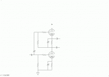
Here is the corrected version. I know it works because I have an amp with this as an output stage. It is single ended in operation. Hi Greg, you are right about the Broskie connection. He showed it as a rough idea that I fleshed out and made work. I was looking at it again to remind myself why the top tube is not a cathode follower but indeed a voltage amplifier when I thought it could be made into a phase splitter. I am not planning to build a push pull amp so I thought I would just throw it out there.
I am trying to get a shop power supply off ebay. If I get it, I will wire this up and see how it works.
Cheers.
Rolf.
I am trying to get a shop power supply off ebay. If I get it, I will wire this up and see how it works.
Cheers.
Rolf.
Attachments
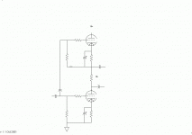
Thank's guys for pointing out my error.  I was rushing my cut and paste job in ms paint.
Broskie's name for this as an output stage, with a transformer where the load resistor is in my corrected schematic, was "Accordion amplifier". Maybe I subconsciously associated accordion with concertina, which is, of course, a kind of accordion. It is sort of similar except instead of one tube and two load resistors and no gain, it has two tubes, one load resistor, and lots of gain! It is sort of like an inside out concertina!
Cheers/
I was rushing my cut and paste job in ms paint. Broskie's name for this as an output stage, with a transformer where the load resistor is in my corrected schematic, was "Accordion amplifier". Maybe I subconsciously associated accordion with concertina, which is, of course, a kind of accordion. It is sort of similar except instead of one tube and two load resistors and no gain, it has two tubes, one load resistor, and lots of gain! It is sort of like an inside out concertina!
Cheers/
Um, sorry, the top one's still a cathode follower.
Here's an article I found about the accordian:
The Tube CAD Journal: The Accordion Amplifier: A new single-ended topology
The top and bottom tubes need to be separately driven e.g. by an interstage transformer with two secondaries.
Here's an article I found about the accordian:
The Tube CAD Journal: The Accordion Amplifier: A new single-ended topology
The top and bottom tubes need to be separately driven e.g. by an interstage transformer with two secondaries.
I do not think the top is a cathode follower, as it will produce gain (I believe).
When working as intended the middle of the RL will be at a constant level with no AC.
The Accordian as described by Broskie may serve a purpose as a power stage, but whether it has any merit as a phase splitter/driver compared to say a gain stage and concertina remains to be seen.
 The Tube CAD Journal: The Accordion Amplifier: A new single-ended topology
The top and bottom are driven by the same signal (with caps to block DC) and should not need an interstage Xformer.
Svein.
When working as intended the middle of the RL will be at a constant level with no AC.
The Accordian as described by Broskie may serve a purpose as a power stage, but whether it has any merit as a phase splitter/driver compared to say a gain stage and concertina remains to be seen.
The top and bottom are driven by the same signal (with caps to block DC) and should not need an interstage Xformer.
Svein.
I do not think the top is a cathode follower, as it will produce gain (I believe).
When working as intended the middle of the RL will be at a constant level with no AC.
No, and no. Does Kirchoff mean anything to you?
The circuit would work better if RL were split into a CF-to-GND component and a plate-to-B+ component, that way the AC voltage on each would be only the individual output, not the total.
The Accordian as described by Broskie may serve a purpose as a power stage, but whether it has any merit as a phase splitter/driver compared to say a gain stage and concertina remains to be seen.
http://www.tubecad.com/articles_2001/Accordion_Amplifier/img5.gif
What the hell. Connecting two tubes in series has absolutely no merit. You can do it in one, without wasting the transformer required to drive the top tube!
Tim
The top tube really is not a cathode follower. It has a bypassed cathode bias resistor. and the grid return is to the bottom of that resistor. The cathode can not follow the grid because the bias resistor and capacitor keep it a a steady voltage Compared to it's "ground", the top of the load resistor, just like the lower tube. The resulting change in plate to cathode voltage makes the top of the load resistor rise in voltage as a result of increased conduction the same amount as the bottom of the resistor is reduced in voltage.
Whether or not it has merits as a phase splitter in an actual amplifier has yet to be seen but I believe it could work.
At the least it is making for some good discussion.
Cheers.
No matter where you go there you are.
Whether or not it has merits as a phase splitter in an actual amplifier has yet to be seen but I believe it could work.
At the least it is making for some good discussion.
Cheers.
No matter where you go there you are.

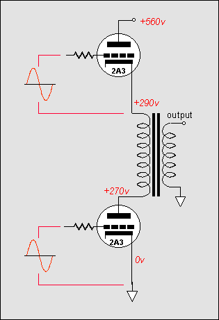
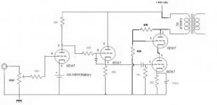
I may have to eat my words. I just put a probe of my oscilloscope on each side of my output transformer. I can't believe I never did that yet. This is on the amp that uses the accordion output. the signals on each side do seem to be grossly mismatched. Here is the circuit.
Attachments
here you will find several phase splitter ideas:
http://www.diyaudio.com/forums/soli...e-ended-related-solid-state-output-stage.html
http://www.diyaudio.com/forums/solid-state/14320-n-channel-only-output-devices-power-follower.html
http://www.diyaudio.com/forums/solid-state/24744-push-pull-using-only-n-channel-mosfets.html
http://www.diyaudio.com/forums/soli...e-ended-related-solid-state-output-stage.html
http://www.diyaudio.com/forums/solid-state/14320-n-channel-only-output-devices-power-follower.html
http://www.diyaudio.com/forums/solid-state/24744-push-pull-using-only-n-channel-mosfets.html
I may have to eat my words. I just put a probe of my oscilloscope on each side of my output transformer. I can't believe I never did that yet. This is on the amp that uses the accordion output. the signals on each side do seem to be grossly mismatched. Here is the circuit.
That's because your upper tube really is acting as a cathode follower, and the lower tube isn't; but they're getting the same input signal. It looks like you're trying to make a SEPP output stage, but you have the 2nd stage arranged as a cathode follower when you need to make it more like a cathodyne, with the anode resistor supplied from the cathode of the top output tube.
Godfrey'
The funny part is, although I read the begging of that article many times, When I got to page three where the add for the glass-ware software is, I thought that was the end and missed the whole section on driving it.
merlinb,
I know it is quite a mind stretch to see the hidden voltage amplifier that looks like a cathode follower. But what I realize now is that the two output sections, effectively, are not getting the same input signal. The top tubes "ground", the bottom of it's cathode resistor, is radically changing in voltage with the signal amplified by the bottom section. the grid needs a signal that "rides?" up and down with the cathode voltage to drive this tube properly.
This is going to need major reworking and will take me quite some time. I am planning to try the cascode like driver with the negative power supply rail sugestedThe Tube CAD Journal: The Accordion Amplifier: A new single-ended topology
Cheers.
Today's lesson - accordians are a bitch to drive properly.
The funny part is, although I read the begging of that article many times, When I got to page three where the add for the glass-ware software is, I thought that was the end and missed the whole section on driving it.
merlinb,
I know it is quite a mind stretch to see the hidden voltage amplifier that looks like a cathode follower. But what I realize now is that the two output sections, effectively, are not getting the same input signal. The top tubes "ground", the bottom of it's cathode resistor, is radically changing in voltage with the signal amplified by the bottom section. the grid needs a signal that "rides?" up and down with the cathode voltage to drive this tube properly.
This is going to need major reworking and will take me quite some time. I am planning to try the cascode like driver with the negative power supply rail sugestedThe Tube CAD Journal: The Accordion Amplifier: A new single-ended topology
Cheers.
Hi Rolf
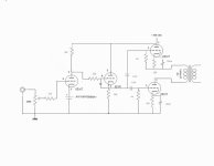
Maybe you could do something like this with the power amp.
It's the same principle as the accordian (series-connected output tubes sharing the voltage equally), but a lot simpler.
If there's a speed problem with the upper output tube, that could be corrected with a small cap across the bottom 47K resistor. Should be OK as is though.
Good luck anyway.
Cheers - Godfrey
Edit: No good for a phase-splitter though...
Attachments
Last edited:
- Status
- This old topic is closed. If you want to reopen this topic, contact a moderator using the "Report Post" button.
- Home
- Amplifiers
- Tubes / Valves
- Phase splitter idea