I've started the design of my first amp. It is meant to be a small PP stereo amp to drive a set of Klipsch Heresey Speakers (circa 1979).
I plan on using all surplus Russian tubes, 6N23P for the input for their low noise, 6N2P for drivers, and 6P1P for the output tubes.
I've modeled it with Lt-Spice, but am a bit frustrated with a couple of things.
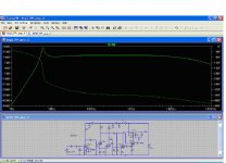
(1) There is a pronounced peak around 7hz. This probably won't matter in the real world with a set of Hammond 1609 transformers. Unless, the system acts like the old BOSE 901 series II systems with the active filter between the line out and in. The amp could end up driving the heck out of the bottom end because of the inefficent speakers. With the feedback I have, this could result in the low frequency sucking up a lot of power.
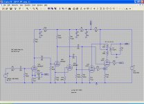
(2) I had to tweak R6 to get a balance between the two differential drives to the grids of U11 and U12. In theory this should not be required.
The schematic does not take into account the UL taps of the 1609 Transformers since I don't yet know how to model them.
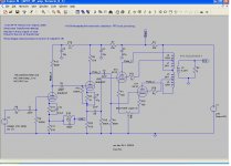
First image is a combined gain plot and schematic from the LTSpice Simulation.
Second image is the schematic in LTSpice.
Comments?
Suggestions?
Thanks.
Steven
I plan on using all surplus Russian tubes, 6N23P for the input for their low noise, 6N2P for drivers, and 6P1P for the output tubes.
I've modeled it with Lt-Spice, but am a bit frustrated with a couple of things.
(1) There is a pronounced peak around 7hz. This probably won't matter in the real world with a set of Hammond 1609 transformers. Unless, the system acts like the old BOSE 901 series II systems with the active filter between the line out and in. The amp could end up driving the heck out of the bottom end because of the inefficent speakers. With the feedback I have, this could result in the low frequency sucking up a lot of power.
(2) I had to tweak R6 to get a balance between the two differential drives to the grids of U11 and U12. In theory this should not be required.
The schematic does not take into account the UL taps of the 1609 Transformers since I don't yet know how to model them.
First image is a combined gain plot and schematic from the LTSpice Simulation.
Second image is the schematic in LTSpice.
Comments?
Suggestions?
Thanks.
Steven
Attachments
Shift one pole 5-10 times, you have all couplings 22n/470K
For example, 220n from driver stage to output toobs.
I would use 6N1P instead of 6N2P, and about 8 mA of current since you go with UL (higher Miller capacitance than when pentode).
One more option: 6N2P on input, 6N23P as a driver.
For example, 220n from driver stage to output toobs.
I would use 6N1P instead of 6N2P, and about 8 mA of current since you go with UL (higher Miller capacitance than when pentode).
One more option: 6N2P on input, 6N23P as a driver.
I did a first order approximation on the spice model by substituting the models as follows:
6P1P - 6AQ5 - 6BQ5, change capacitance, Mu values
6N1P - 6SN7 change capacitance, Mu values
6N2p - 12AX7 change capacitance, Mu values
6N23P - 6DJ8 change capacitance, Mu values
I used Duncan Munro's file dmtriodep.icn from http://www.duncanamps.com
I hope to refine the models as I learn more about PSpice.
I changed some of the resistor values to get U1 up to 1.8mA cathode current, U2a/b up to 2.64mA cathode current(combined) and measured (PSpice) the output cathode current at 51.5ma.
This gives plate dissipation for the tubes at:
6N23P - .335W
6N2P - .24W
6P1P 12.4W (12W limit)
The 6P1P is a tad hot and I'll need to increase the cathode resistor value to get it down a bit to play it safe.
Changing one of the coupling caps to 220nF got rid of the pronounced peak in frequency response.
Thanks all.
Steven
") Let us know how it sounds !
Let us know how it sounds !While the "taste is in the Pudding" I prefer to do a bit of 'what if' with the simulator before hitting the hardware. It oft time saves a lot of 'Oh! SH**!'
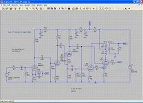
I found I had a problem with the 6N2P model for some reason. I got better results with the 6N23P model, and made some tweaks.
I think the phase splitter is better in this iteration.
Steven
I found I had a problem with the 6N2P model for some reason. I got better results with the 6N23P model, and made some tweaks.
I think the phase splitter is better in this iteration.
Steven
Attachments
I tried several 6N2P models and they all wanted to go into cut-off, where-as the 6N23P and 12AX7 models do not.
The problem I've seen with PSpice is that they all are approximations that will get you close, but you have to build the circuit and tweak it in to get it where you want it (I'm currently using LT Spice, but also have an old 16 bit version of ICAPS/4. I had hoped to get a free update to 32bit, but I don't think that will happen).
The current design is close, but the cathode current is wrong on the output tubes. This is wrong whether I use a 6AQ5, 6BQ5, or 6V6 model. I am comparing the results to the cathode current vs grid bias with 250V plate voltage and about -10.5V grid bias yielding a 210 Ohm cathode resistor. Those parameters should put me near 50mA cathode current, but the simulation says 30mA. This is way off, even ignoring that I should be able to drop it to 190 Ohm when Screen current is accounted for.
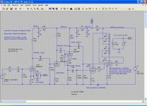
I've mapped the cathode currents, plate voltages and gain for all stages.
Time to stick a fork in it and call it done.
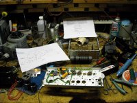
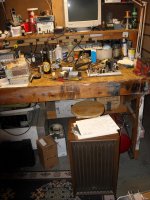
I'll start pulling the parts together when I get back from visiting my dad this weekend. I'll build a prototype before I lay out the final chassis. The prototype will be on an aluminum chassis from a Tek 545 oscilloscope I'm using for parts.
Steven
The problem I've seen with PSpice is that they all are approximations that will get you close, but you have to build the circuit and tweak it in to get it where you want it (I'm currently using LT Spice, but also have an old 16 bit version of ICAPS/4. I had hoped to get a free update to 32bit, but I don't think that will happen).
The current design is close, but the cathode current is wrong on the output tubes. This is wrong whether I use a 6AQ5, 6BQ5, or 6V6 model. I am comparing the results to the cathode current vs grid bias with 250V plate voltage and about -10.5V grid bias yielding a 210 Ohm cathode resistor. Those parameters should put me near 50mA cathode current, but the simulation says 30mA. This is way off, even ignoring that I should be able to drop it to 190 Ohm when Screen current is accounted for.
I've mapped the cathode currents, plate voltages and gain for all stages.
Time to stick a fork in it and call it done.
I'll start pulling the parts together when I get back from visiting my dad this weekend. I'll build a prototype before I lay out the final chassis. The prototype will be on an aluminum chassis from a Tek 545 oscilloscope I'm using for parts.
Steven
Attachments
Well, I finally got off my keyster and started the prototype.
Now that I have a current limited 100-350V power supply built I have started building my first amp.
I was tempted to fiddle with the phase splitter, but thought "No, leave it alone and just build it!", so I have the first gain stage and phase splitter wired up along with the filaments, and a delay tube for the B+.
I've done a power test on the filaments and delay tube. All looks good so far.
Attachments
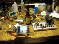
The Prototype Sven PP is up and running!
Weeeeeeeeeeeeeeeeeeeeeeeeeee!
I ran power up tests for bias conditions and found I had a problem with my bench supply and could only get 220V out of it with the load I was running. So I did the initial tests at 220V B+ and 180V on the screens.
This is with an old output transformer that is supposed to be from a Lafayette amp. I have several different OPTs I want to try before switching to the Hammond 1609s I expect to run with it.
After confirming bias conditions (running a bit cool at 32mA on the output cathodes) I ran some gain measurements. I adjusted a signal generator to get 2.8Vrms out on a 8 ohm resistive load and then measured the input required to achieve this (1W out).
I got:
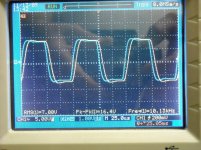
20Hz 0.432Vrms Waveform distorted at driver and output due to low B+
50Hz 0.254Vrms
100Hz 0.256Vrms
1KHz 0.236Vrms
10KHz 0.236Vrms
20KHz 0.208Vrms
30KHz 0.190Vrms
40KHz 0.180Vrms
Powered it down, disconnected the load and signal generator and hooked up a Kenwood KL5050 and CD player.
First up YES Fragile, Roundabout - muddy muted mids and guitar sounds strained. Volume won't go up above "background music level"
May need to add an additional gain stage since I haven't hooked up the GNFB yet.
So, I think "What if I switch out the front end tubes ?". This was with the 6N23P in the first stage and driver position, which it was designed for.
Switched both to 6N1P - Voices still a bit muddy, but the guitar sounds more 'real'.
6N6P - between 6N23P and 6N1P. not impressive.
6N2P - Damn! Volume up at least 9dB. Guitar is right there, Voices are clean and clear.
At this time I shut it off and ejected the CD, then went upstairs and got the wife to bring one of her CDs down and played Beatles "Let it Be".
After listening for 5 minutes she asked "Can I have one of those upstairs?"
YES!
After she went back up stairs I listened to Billy Joel Storm Front, Jefferson Airplane "Jefferson Airplane" (1989) and Bonnie Raitt "Sweet Forgiveness".
I'm really impressed with how well this little amp compares with the SS amps we have (Sony STR-5800, Philips 951 and Magnavox 931Pro - wife's system upstairs ).
I'm also surprised at the difference switching tubes made. I suspect this could be compensated for by changing the bias and load resistance.
I may have some time to play with that after I switch out the OPTs and try different ones. I also need to correct the bias on the screens (220V and should be 200V) and the cathode bias (32ma vs 50mA target with 70Ma max).
My power supply consists of an AnTek AN-1T200 with a KBU6K bridge rectifier followed by a 47uF 450V cap, 7H (Gap Core switching power supply) inductor, and a 220uF 450V final cap. The Plates of the output tubes connect here, then there are R-C filters for the driver and preamp tubes.
As my last test of the evening, I hooked up a 60uF 440Vac Motor Run capacitor across the 220uF 450Vdc cap in my power supply with a switch shorted by a 220K resistor. My reasoning is that once the cap is charged up to the average DC value, I can switch between the cap in and out of the circuit to see if it makes a 'sonic' difference.
I can see no discernible difference, and conclude that for this amp it makes no difference. It may in larger amps, or amps with a lower filter capacitance to load ratio.
Overall I'm really happy with this amp, and foresee building several stereo units once I'm finished tweaking it.
Steven
Weeeeeeeeeeeeeeeeeeeeeeeeeee!
I ran power up tests for bias conditions and found I had a problem with my bench supply and could only get 220V out of it with the load I was running. So I did the initial tests at 220V B+ and 180V on the screens.
This is with an old output transformer that is supposed to be from a Lafayette amp. I have several different OPTs I want to try before switching to the Hammond 1609s I expect to run with it.
After confirming bias conditions (running a bit cool at 32mA on the output cathodes) I ran some gain measurements. I adjusted a signal generator to get 2.8Vrms out on a 8 ohm resistive load and then measured the input required to achieve this (1W out).
I got:
20Hz 0.432Vrms Waveform distorted at driver and output due to low B+
50Hz 0.254Vrms
100Hz 0.256Vrms
1KHz 0.236Vrms
10KHz 0.236Vrms
20KHz 0.208Vrms
30KHz 0.190Vrms
40KHz 0.180Vrms
Powered it down, disconnected the load and signal generator and hooked up a Kenwood KL5050 and CD player.
First up YES Fragile, Roundabout - muddy muted mids and guitar sounds strained. Volume won't go up above "background music level"
May need to add an additional gain stage since I haven't hooked up the GNFB yet.
So, I think "What if I switch out the front end tubes ?". This was with the 6N23P in the first stage and driver position, which it was designed for.
Switched both to 6N1P - Voices still a bit muddy, but the guitar sounds more 'real'.
6N6P - between 6N23P and 6N1P. not impressive.
6N2P - Damn! Volume up at least 9dB. Guitar is right there, Voices are clean and clear.
At this time I shut it off and ejected the CD, then went upstairs and got the wife to bring one of her CDs down and played Beatles "Let it Be".
After listening for 5 minutes she asked "Can I have one of those upstairs?"
YES!
After she went back up stairs I listened to Billy Joel Storm Front, Jefferson Airplane "Jefferson Airplane" (1989) and Bonnie Raitt "Sweet Forgiveness".
I'm really impressed with how well this little amp compares with the SS amps we have (Sony STR-5800, Philips 951 and Magnavox 931Pro - wife's system upstairs ).
I'm also surprised at the difference switching tubes made. I suspect this could be compensated for by changing the bias and load resistance.
I may have some time to play with that after I switch out the OPTs and try different ones. I also need to correct the bias on the screens (220V and should be 200V) and the cathode bias (32ma vs 50mA target with 70Ma max).
My power supply consists of an AnTek AN-1T200 with a KBU6K bridge rectifier followed by a 47uF 450V cap, 7H (Gap Core switching power supply) inductor, and a 220uF 450V final cap. The Plates of the output tubes connect here, then there are R-C filters for the driver and preamp tubes.
As my last test of the evening, I hooked up a 60uF 440Vac Motor Run capacitor across the 220uF 450Vdc cap in my power supply with a switch shorted by a 220K resistor. My reasoning is that once the cap is charged up to the average DC value, I can switch between the cap in and out of the circuit to see if it makes a 'sonic' difference.
I can see no discernible difference, and conclude that for this amp it makes no difference. It may in larger amps, or amps with a lower filter capacitance to load ratio.
Overall I'm really happy with this amp, and foresee building several stereo units once I'm finished tweaking it.
Steven
Attachments
Shift one pole 5-10 times, you have all couplings 22n/470K
Is that the same procedure they call "slugging the dominant pole"?
For frequencies highly attenuated, even the worst phase shift won't
make an oscillator. But at corner frequency of unity loop gain (or NFB)
you had better have 90deg phase shift or less... Thus the slope that
leads into your corner can't be any sharper than -6dB. or is it -3dB?
Or to put it another way: If you are gonna have a bunch of filters
rolling together at some higher rate (and phase shift). It had best
already have been attenuated below unity loop gain by a filter with
a lower corner frequency and lesser slope.
Am I telling the story straight, or do I got it messed up somehow?
I don't wanna be repeating nonsense, but it happens sometimes...
Last edited:
My problem originally was that I had added an additional gain stage and hadn't changed the polarity of the NFB. I had PFB instead.
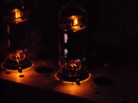
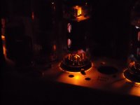
I just took a couple of pix of the inside of the output tubes. It looks like there is a fine blue glow along the screen support rods as seen through the opening sin the plate.
Opinions?
I've already changed the CRC to get the screens down to 195V (200V max) with a plate to cathode voltage of 265V (250V Max) and cathode current of 38mA (plate max 70, screens are probably at 3mA each,so only 35mA plate current).
I suspect if I get my plate current up to 50mA I'll get the Plate to cathode voltage down close to 250V, so I just need to decrease the cathode resistor values.
Attachments
Well, I tried to change the bias on the outputs tonight and ran into a really strange situation.
I expected to hit 10.5V cathode bias at 53-55mA ( 50mA plate plus 3-5mA screen current) at 250 on the plate to cathode and 200V screen to cathode.
I have dropped the cathode resistors all the way down to 94.4/86.3 Ohms to get 55.3 and 55.8mA cathode current on the two cathodes(5.22 and 4.83V respectivly).
I don't see why the grid voltage is off so much from the tube spec.
I am not confused by the differences in tube bias points as I have seen about a 10% variation in Gm on these tubes and haven't even measured mu.
I swapped the phase splitter from a 6N1N to a 6N2N, then a 6N23P and finally a 6DJ8 without changing the tonal quality. This confirms that the first gain stage is the one I need to work on to see if I can get it straightened out for the 6N23P and understand what is effecting it.
What gives with the bias point of the 6P1Ps?http://tubedata.milbert.com/sheets/113/6/6P1PEV.pdf
Hey Gimp,
Absolutely, the tube family you are using needs 5-10mA Ia to work at their best. You run them at a fraction of this. You can begin at 120V/5mA and go from there.
This confirms that the first gain stage is the one I need to work on to see if I can get it straightened out for the 6N23P and understand what is effecting it.
Absolutely, the tube family you are using needs 5-10mA Ia to work at their best. You run them at a fraction of this. You can begin at 120V/5mA and go from there.
I must have messed up when I modified the 6DJ8 model for the 6N23P. I would have expected the FFT to have shown more distortion with the 6N23P under-biased the way it is.
I'll go back and check the models when I get home (I'm at my pop's in SC taking care of him for the weekend.) and look at changing the bias and load to try the other three tubes to verify they get rid of the veiled/muddy performance.
This brings to mind some descriptions I've read on capacitor evaluations that looked like they were describing similar accoustic distortion.
The under-biased tube should be compressing the signal, no? Could some non0-linearity in capacitors cause the same compressive distortion or would capacitors exhibit another form of distortion that would cause the same accoustic signature?
Last edited:
Gimp
In some tubes the blue color is normal, don't worry about it.
On another note: I have just ordered off eBait a p-p 6P1P amplfier (cheap China stuff) and have been looking around for decent designs with the 6P1P tube. (Originally I ordered the EL84 version but I changed the order to this one when I saw the prices of the EL84 and then when investigating the specs of the 6P1P I liked that tube a lot more in spite of the slightly lower output).
Have you investigated the "elcheapo" amplifier by Eli Duttman which seems to be about the best bang for the buck?
The just ordered amp will be a donor to create the "elcheapo".
Regards
Marinus
I'll look over the "elcheapo", but I still plan on building this amp as I have almost everything on hand now (All the Iron, tubes, most caps, half the resistors, etc.
I've upped the bias on the input stage and that corrected the problems I was seeing. 6DJ8s, 1P2P, 1P23P sound Much better, 6N6P still slightly veiled, but to be expected at 1.8mA bias.
I'll up the bias to 2.3mA, 7.5mA, 15mA, and finally 11.2mA and try it again after I finish testing with the Hammond 1609.
Right off I hear the base everyone talks about. Not really objectionable, but noticeable none the less. Really comes through on Bonnie Raitt Sweet Forgiveness base guitar and drums.
I will probably use the new Hammond 1609s for the wife’s system and the salvaged Olson’s for my garage system. I’ll have to ponder the alternatives for the system in the Den with the main stereo and TV.
IN reviewing the specs on the transformers for the elcheapo, I noticed they are 6600 ohm p-p. The 6AQ5 is spec'd at 10000ohm P-P and will produce a bit less power with the 6600 ohm p-p transformer.
However, according to Beam Power Tubes by O.H. Schade (Publication No. ST-59, March 1938) this will result in considerable less harmonic distortion. Whether this is true or not I don't know.
If I ever figure out how to use the FFT function on my scope, It might be interesting to try different taps on an output transformer with an 8 ohm load (or change the resistive load) and see how it effects the spectral response of harmonics.
- Home
- Amplifiers
- Tubes / Valves
- Sven 6P1P PP Amp