Steven
- Try to get the 6P1P-EV tubes, they have less noise but are harder to find. (I just order a batch of 10). Ratings are slightly different, the g2 rating is lower.
- Take a look at Lundahl's website. There is a design for a SE EL34 by Claus Byrith and he is using the speaker winding also for the cathode feedback connection. (Similarly to the old Quad II but that was PP) MacIntosh used the same principle and the tubes in those amps run forever.
- I pm'd you about the transistors for the RAT tube tester. Thanks.
- For a source of power transformers keep an eye on old HAM radio gear, I just stripped a Kenwood "hybrid" transceiver (TS-520) and it has a transformer that will give negative bias, all the 12.6 V you ever want and a 2 x 400 V which is used for 250 mA @ 800V. But that can be changed to a normal 2 x 400V ~ 500V @ 500 mA high voltage supply. It also has 210 and 300V windings. Perhaps not suitable for this project but worthwhile to keep in mind.
- Just bought a cheap Chinese 6P1P amp off eBay that I want to use as a base (will mod it), cannot use the Claus / MacIntosh / Quad feedback loop because this is PP and it would need two speaker windings. Am intending to try out triode PP mode (don't need a lot of power, the elcheapo design is coming to mind but leaving the original 6N3P drivers in place but rolling the tube to the 6N3P-EV.) I opted for the surface shipping, have confirmation of the order but not yet of the shipping.
- In ham radio there is a lesser know article by G2DAF and he discusses the g2 voltage and need to make sure that the g2 voltage does not increase when the anode current decreases (non linear behaviour). In audio there is the ultra linear approach but for transmitters he is using a different approach. However it is a worthwhile read for getting an insight in tube behaviour.
happy building to you
I buy -EV (or EB) whenever I can find them.
I probably will order another 30-50 6P1P-EVs in the next few days just to stock up.
Once I'm satisfied with the input and driver stages I'll stock up on tubes for them as well.
I found Lundahl's site and will try to find G2DAF as well Thanks.
I get my tubes from
I probably will order another 30-50 6P1P-EVs in the next few days just to stock up.
Once I'm satisfied with the input and driver stages I'll stock up on tubes for them as well.
I found Lundahl's site and will try to find G2DAF as well Thanks.
I get my tubes from
Dang, forgot to add the shop.
eBay Store - High-End-tubes: High-End Tubes, Rare Vintage tubes, Nixie tubes
Shipping usually runs in the 20-24 day range, but good comm and reliable so far (three orders received, forth submitted tonight).
eBay Store - High-End-tubes: High-End Tubes, Rare Vintage tubes, Nixie tubes
Shipping usually runs in the 20-24 day range, but good comm and reliable so far (three orders received, forth submitted tonight).
Well, the amp is finally doing what I expected it to. The screen voltage being too low was part of the problem as was the cathode bias.
I've tried RLD bias, Cathode bias (resistor), and my own Voltage bias (LED stack or Zener driving a TIP41 as a voltage sink. The LED string or Zener was from base to collector and a 68 ohm resistor from base to emitter as a voltage sink.
I've run the bias up to the point where I could barely see the plate seam start to turn red (all lights out) and could get over 14W out of it with 69mA cathode current and 252V B+.
I cranked it back down to 60.15mA cathode current which with 2.5mA screen current leaves me with 57.65mA plate current. Still a tad hot and I'll have to adjust it down some more. Zeners and LEDs have the disadvantage of only offering discrete voltage drops and thus discrete current steps.
I'm thinking of adding a small trimpot in series with the LEDs to allow me to tweak the reference voltage and thus the current.
That aside, I'm presently seeing :
B+ - 268V
Cathode Voltage - 8.64V / 7.71V (two output tubes)
Cathode Current - 61.75mA / 60.15mA
Screen Voltage - 252V / 253V
Screen Current - 3.25mA / 3.8mA
Plate voltage - 253V / 254V
Grid drive 28Vrms, Plate voltage 146Vrms into a 10Kp-p transformer with 8.3 ohm load resistor (Hammond 1609).
I can get about 7.58W out before clipping onset takes place (no increase in output voltage with an increase in input voltage). Max output power is 10.85W at 1KHz, but I'm sure this is producing massive distortion.
Sound is FanF&^*%ingtastic!
So, my next question is:
How do I use this prototype to match my output tubes? I've got 30 6P1P-EV tubes and another 50 on order.
I'd like to match them in pairs.
I'm sure some tubes will fall outside the acceptable range for matching and I'll use these for abusive treatment (how much power can I deliver into a 8ohm 100W load before things go PooF!).
If I set the plate current to a chosen value like 50mA,
I can now measure Gm (0.1V in and measure I-out with a 1 Ohm plate resistor).
I can measure mu as Vp divided by Vg (ac).
I can measure Vgrid for the given 50mA plate current.
Given that I'll be adjusting the cathode voltage to adjust the plate current to 50mA, I believe that the gate voltage becomes the least important measurement. Is this a valid assumption?
Once I have these numbers for each tube how do I select the matching? Is mu more important than Gm? Or is Gm more important than mu for the output tubes?
Thanks.
Steven
....
Once I have these numbers for each tube how do I select the matching? Is mu more important than Gm? Or is Gm more important than mu for the output tubes?
Emission test is useless. I like the RAT design and as you are aware I am building one up. Even the Mercury 1000 will match it within a certain tolerance. But be aware that a tube matched at 100 V may not be matched at its operating voltage of 250 V. The best matching is to match them at 250 and then again at 150. The other item to check is to drop the filament voltage 10% and see what that is doing to the transconductance.
Speaking about filament voltage: run them at nominal filament voltage, if running them 10% above or below then you can easily shorten the live by a factor 3. I always check the voltages and if not close enough then I'll do something about it.
Regards
Amadeus, I think you miss-understood me. I'm not doing an emission test.
I am wanting to test the tubes in "the amplifier" under actual operational conditions rather than in a tube test set.
I will adjust the plate current to 50mA so that the tubes are run as they will in the amp.
What is the most important under real world conditions? How do I match them?
I am wanting to test the tubes in "the amplifier" under actual operational conditions rather than in a tube test set.
I will adjust the plate current to 50mA so that the tubes are run as they will in the amp.
What is the most important under real world conditions? How do I match them?
Sound is FanF&^*%ingtastic!
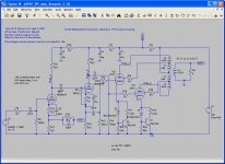
Can´t be the schematic from post#8, I presume
") ? Do you have a fresh schematic?
? Do you have a fresh schematic?Ignore the notes, I haven't updated them in a while.
I'll go back through the prototype in the next day or so (Family coming today instead of yesterday so I'm cooking today) and verify it against the schematic to be sure all values etc are correct.
I have not tried GNFB yet, so that is not hooked up.
I tried 8 tubes yesterday with Gm varying from 4000 to 4950. Two were above 4900, the rest below 4400. The ones below 4400 all biased up fine and ran great. The two with Gm above 4900 went red-plate in seconds! Plate current was over 120mA!
I plan on adding a tweak for trimming the bias next. Then I'll try GNFB to see how it effects operation.
Attachments
Amadeus, I think you miss-understood me. I'm not doing an emission test.
I am wanting to test the tubes in "the amplifier" under actual operational conditions rather than in a tube test set.
I will adjust the plate current to 50mA so that the tubes are run as they will in the amp.
What is the most important under real world conditions? How do I match them?
Failing having a tube tester / wanting to use a tube tester I am thinking that you can try something along the following lines: (have not tested this but it - may work)
- you want to match the tubes for the same amplification factor
- dc and ac amplification are not necessarily going to give the same results
- a computer can easily generate an audio signal (alternatively use a real audio generator - you can also have some test CD with a constant tone)
- you'll need to be able to feed this into the amp and make sure (using an AC voltmeter) that the voltages going to the grids of the finals are exactly the same (ensuring that the splitter is perfectly balanced)
- have not looked at your latest design. assuming (dangerous to assume) that you have used a common cathode resistor and a bypass capacitor for the to finals (cathodes coupled together) seperate these and only use a resistor for each tube of double the value (we want to be able to see the AC there too hence no capacitor, double the value because only one tube is feeding the resistor)
- hopefully the amp is stable without feedback. disconnect the feedback.
- check that the DC through each tube is the same, if not then that is already reason to assume they are not matched
- feed the ac signal and measure the AC voltage through each tube.
- here I am getting on a slippery slope; you may want to have only one final into ensure you are not having one tube influencing the measurements of the other.
The AC voltage of each tube should be at least within 10 %, normal is within 5% and real good matching goes within 2%. Use a digital meter, absolute values are not important since you are only interested in matching.
Let us know if this works, Cheers for now.
PS
you may just runa check that at 100 Hz, 1000 Hz and 10 kHz the volatges stay the same, some tubes are duds and may work fine at 100 Hz but give up at higher frequencies. Similarly normally these tests are done with 100mV AC input to the finals but you may want to check at higher values too, some tubes look fine at low power but show a large discrepancy at higher levels.
you may just runa check that at 100 Hz, 1000 Hz and 10 kHz the volatges stay the same, some tubes are duds and may work fine at 100 Hz but give up at higher frequencies. Similarly normally these tests are done with 100mV AC input to the finals but you may want to check at higher values too, some tubes look fine at low power but show a large discrepancy at higher levels.
The two tubes with 4900+Gm required greater than -11V grid to cathode bias to get below 55mA Plate current (red plate). Once I had them biased correctly they sounded fine. I've added a 100 ohm trim pot on top of the Zener to allow me to tweak the bias current. I'll play with zener values to get the best results (compatible with most tubes) once I get more tubes.
matching
Steven, since this amplfier is running in class A matching is not as critical as when running in AB or B where there is a cutoff of the other "half" of the signal and the matching is required to prevent crossover distortion.
In fact there are some engineers in the commercial world who regard matching for class A push-pull amplifier unnecessary.
I think mu and gm are just the same measurements although one manufacturer will use one and then the other manufacturer the other. (only getting now more interested in the different measurement methods, relatively new to tube testing), it may well be that it is only due to the battle between the US and Europe about "the best tube" etc etc.
Today on ePray I came across some figures about a tube (which was being advertised) and that had both figures but the ratio between the figures was exactly the same indicating to me not to get a hangup about this.
Hope this helps.
What is a good sound card to work with "audioTester"?
I've got an old Soundblaster II compatible card, but it does not go past 22KHz (44.1KHz sample rate limited?).
I wired up a patch panel today with RCA jacks for both R and L channels for Sound card Out and Sound Card In. Then I plugged RCA male to male cables in as loop-backs figuring 0db flat response but saw a drop around 10KHz that leveled out to 22KHz, then dropped like a rock (44.1KHz sample rate?).
Initial tests with it show poor s/n for the card in loop-back mode.
What is a good reasonable priced card to use for testing?
What is a good sound card to work with "audioTester"?
I've got an old Soundblaster II compatible card, but it does not go past 22KHz (44.1KHz sample rate limited?).
I wired up a patch panel today with RCA jacks for both R and L channels for Sound card Out and Sound Card In. Then I plugged RCA male to male cables in as loop-backs figuring 0db flat response but saw a drop around 10KHz that leveled out to 22KHz, then dropped like a rock (44.1KHz sample rate?).
Initial tests with it show poor s/n for the card in loop-back mode.
What is a good reasonable priced card to use for testing?
Cannot help you there, I've always had high end IBM laptops but Lenovo has taken over and the quality has gone down: previously there was a line input but it has disappeared. Many were using these laptops for studio mixing purposes and they are quite upset about the line input having disappeared.
Same as using the computer as an oscilloscope / spectrum analyzer (handy when you use white noise / pink noise to test a speaker or amplifier to see if the response curve is flat enough). What software are you using? Alternative use a test CD from Denon which has all the frequencies and which is well calibrated. IMHO that would be the cheaper and safer option and frankly I have always been quite hestistant to hook up my laptop to other high electronic gear: you make a mistake and fry the computer....
I've got an old clone computer in the garage (Ahtelon 600 maybe) that I use for internet access to look up parts, etc while working out there.
I got the trial copy of "audio Tester V2.2" that I'm trying to work with. The current card is an old SB II card (or so says the bios).
audioTester
When running a frequency sweep from 20Hz to 60KHz, I see that the output abruptly drops around 22KHz and presume it is because the old sound cards sampled at 44.1K, which would limit the BW to 22KHz. I'd like to be able to test out at least to 40KHz and preferably 60KHz or more.
I've not looked at computer h/w much in the past few years and am not familiar with the sound cards available now.
I suspect something like the Sound Blaster Audigy SE would work since it is spec'd at 24-bit/96KHz recording and playback with 100dB s/n. However, we all know how specs are.
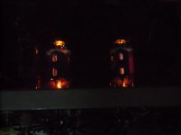
Today at the suggestion of one of the members I went back to simple cathode bias. 200 Ohm cathode to ground gives me 11.02V for 55mA cathode current minus 3.75mA screen current leaves me with 51.35mA plate current.
At 253V Cathode to Plate I've got 12.99W plate dissipation and a slight red fin on one plate so I'll increase the cathode resistors to 220+ Ohms.
The circuit is much less sensitive to Gm variation as far as the plate current running away which is very good.
Out of eight tubes with Gm varying from 3900 to 4950, only the 4950 tube seems to want to go red plate with a 220 Ohm cathode resistor. I can go up to 230 ohms and the bias voltage will go to 11.75V and still glow in the dark. I can't really see it if the overhead lights (17W CFLs) are on. If the bench lights (dual 45W 48" Florescents) are on I can't see it at all.
Attachments
Last edited:
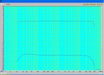
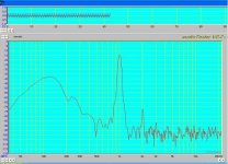
I finally got audioTester working after a fashion. I'm still having issues with occasional stack overflows and other weird problems that may be due to my decrepit system in the garage (Asus K7M with an Athalon 800).
Frequency sweep has a slight hump (<1dB) at the low end, and flat from 100Hz from out to around 40KHz (-3dB point). The top plot is the right channel looped back to itself. The lower plot is the left channel driving the amp, and the output of the amp driving the input with a 10:1 divider.
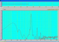
I got the fft and sweep to run, but because I installed a 10:1 resistor divider and anti-parallel diode protection (1N4148) network on the resistor to ground, the first plot is off slightly (3dB?). The second FFT was with the top of the resistor divider shorted, so no attenuation.
FFT in particular seemed to be very sensitive to the gain setting on the Output Mixer Level.
And I haven't figured out why the Line Out keeps getting set to Mute! Stupid computer (Yea Bill, I'm talking to you!). I still need to find out if the Sound Blaster Audigy SE is reasonable for this application or if I need a better sound card, since I can't seem to get it to operate in 24bit input at 192KHz sample rate. I get red text stating "mmsystem: format isn't supported". I can only get it to operate in 16 bit mode.
Frequency sweep has a slight hump (<1dB) at the low end, and flat from 100Hz from out to around 40KHz (-3dB point). The top plot is the right channel looped back to itself. The lower plot is the left channel driving the amp, and the output of the amp driving the input with a 10:1 divider.
I got the fft and sweep to run, but because I installed a 10:1 resistor divider and anti-parallel diode protection (1N4148) network on the resistor to ground, the first plot is off slightly (3dB?). The second FFT was with the top of the resistor divider shorted, so no attenuation.
FFT in particular seemed to be very sensitive to the gain setting on the Output Mixer Level.
And I haven't figured out why the Line Out keeps getting set to Mute! Stupid computer (Yea Bill, I'm talking to you!). I still need to find out if the Sound Blaster Audigy SE is reasonable for this application or if I need a better sound card, since I can't seem to get it to operate in 24bit input at 192KHz sample rate. I get red text stating "mmsystem: format isn't supported". I can only get it to operate in 16 bit mode.
Attachments
Last edited:
I finally got audioTester working after a fashion. I'm still having issues with occasional stack overflows and other weird problems that may be due to my decrepit system in the garage (Asus K7M with an Athalon 800).
Frequency sweep has a slight hump (<1dB) at the low end, and flat from 100Hz from out to around 40KHz (-3dB point). The top plot is the right channel looped back to itself. The lower plot is the left channel driving the amp, and the output of the amp driving the input with a 10:1 divider.
I got the fft and sweep to run, but because I installed a 10:1 resistor divider and anti-parallel diode protection (1N4148) network on the resistor to ground, the first plot is off slightly (3dB?). The second FFT was with the top of the resistor divider shorted, so no attenuation.
FFT in particular seemed to be very sensitive to the gain setting on the Output Mixer Level.
The analog input clips with 300mV. Other than this, it should not had any effect on the distortion showed.
And I haven't figured out why the Line Out keeps getting set to Mute! Stupid computer (Yea Bill, I'm talking to you!).
I still need to find out if the Sound Blaster Audigy SE is reasonable for this application
It depends. Distortion readings are always higher than actual in the sub 100 Hz region. If you can live with that and the 16bit S/N ratio..
or if I need a better sound card,
I think you need. If 48 kHz is o.k as an upper limit, then the M-Audio 96 pci is very nice. For 96kHz, you need the 192, or an ESI Juli@, or the EMU 1212.
since I can't seem to get it to operate in 24bit input at 192KHz sample rate.
Because it doesn't support it via the analog inputs. Mine- an older version, 5 years old- samples with 44/16 bit. Claimed 24/96 works only for digital signals.
I get red text stating "mmsystem: format isn't supported". I can only get it to operate in 16 bit mode.
Sorry for writing between the lines of your message, i just wanted to comment on the specific points.
I believe you do everything the right way: first simulating to get a rough idea if the topology works and get ballpark values for voltages, resistors e.t.c.
Then building-measuring-listening and adjusting circuit parameters.
Very well done!
Greetings from Athens (Greece)
Konstantinos
Thanks, I'll probably hold off on the sound card till I get Pete M's interface build and am more familiar with the system.
If I understand it correctly, to measure THD at 1W with an 8 ohm load I adjust the input 1KHz (or whatever frequency I'm testing at) to 2.828VRMS in. To measure at 32mW (my normal listening level with my speakers) I adjust the peak to .506Vrms and measure the peaks. Take all the harmonics and use the values to calculate the THD as the sqr-rt of the sum of the squares of the peak values.
The only issue with going over about 50mW is that the peaks may overdrive the input of the sound card, hence the 10:1 divider and diode clamps for higher measurements. I have to compensate for this as the measured values are 20dB lower than actual : V dB=20 Log (Vo/Vi) =20 Log (10/1) = 20dB?
Is this correct?
IM distortion measurements are similar, except I'm using two frequencies (440Hz and 1KHz?) as the input. No?
Thanks.
Steven
Ignore the notes, I haven't updated them in a while.
I'll go back through the prototype in the next day or so (Family coming today instead of yesterday so I'm cooking today) and verify it against the schematic to be sure all values etc are correct.
I have not tried GNFB yet, so that is not hooked up.
I tried 8 tubes yesterday with Gm varying from 4000 to 4950. Two were above 4900, the rest below 4400. The ones below 4400 all biased up fine and ran great. The two with Gm above 4900 went red-plate in seconds! Plate current was over 120mA!
I plan on adding a tweak for trimming the bias next. Then I'll try GNFB to see how it effects operation.
Steven, just dredging this thread up again to see if you have updates particularly on the NFB needed. Any updates on the schematic you posted?
Your experiments seem to be paralleling what we are doing with the Meng Yue 6P1 (see the Mengyue schematic thread).
We also have not attacked the feedback aspect, just running without at the moment while we get the input stages to behave. I hated the original paraphase the Meng had.
Gary
- Home
- Amplifiers
- Tubes / Valves
- Sven 6P1P PP Amp