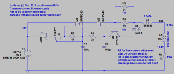
In case people are interested, this is my filament supply for my 26 preamp. My aim was to get as ripple free constant current through the filament as possible, a high impedance looking from the filament to the power supply, and a low impedance looking to the bias resistor/ground.
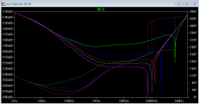
For what it's worth, here's a simulation of the current for various values of L2: 1mH, 10mH, 30mH, 50mH, and 100mH (1R DCR, 50pF parallel capacitance). The green line is for 1mH, and the rest go lower in dB as the inductance gets higher.
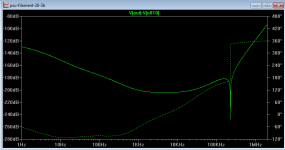
The third plot shows the voltage across the filament; changing the dB values positive would give the line rejection of this circuit.
I am aware that reality and simulation are not the same; the simulation results are here only for illustration purposes.")
The exact values for R3 and R6 should be chosen in real life via measurement. But good values to start with would be so that the parallel value of R3 and R6 be equal to sum of Q1 base-emitter voltage drop (approx. 0.65V) and the voltage drop across the LED (in my case approx. 2V), divided by the desired current through filament supply (in my case I aimed for about 1.045A).
I cannot stress the importance of using large heat sinks for the power mosfets. And yes, the large voltage drop across the mosfets is necessary, so that they can do their job properly.
Edit: oh, I forgot to mention, 100R-220R gate resistors for the power mosfets M1 and M2 may be employed if necessary.
For what it's worth, here's a simulation of the current for various values of L2: 1mH, 10mH, 30mH, 50mH, and 100mH (1R DCR, 50pF parallel capacitance). The green line is for 1mH, and the rest go lower in dB as the inductance gets higher.
The third plot shows the voltage across the filament; changing the dB values positive would give the line rejection of this circuit.
I am aware that reality and simulation are not the same; the simulation results are here only for illustration purposes.
The exact values for R3 and R6 should be chosen in real life via measurement. But good values to start with would be so that the parallel value of R3 and R6 be equal to sum of Q1 base-emitter voltage drop (approx. 0.65V) and the voltage drop across the LED (in my case approx. 2V), divided by the desired current through filament supply (in my case I aimed for about 1.045A).
I cannot stress the importance of using large heat sinks for the power mosfets. And yes, the large voltage drop across the mosfets is necessary, so that they can do their job properly.
Edit: oh, I forgot to mention, 100R-220R gate resistors for the power mosfets M1 and M2 may be employed if necessary.
Attachments
Last edited:
And yes, the large voltage drop across the mosfets is necessary, so that they can do their job properly.
This is the first reason why MOS pass devices are not used in my 26 filament supply! There are other problems with them. But 60W of waste heat for 2x 1.5W filament (stereo) is too much for most of us.
Right, Rod. I could make it more efficient, and it would be quite easy to redo the circuit with power bjts, but the performance would not be the same. Even so, lowering the input voltage to 25V (about 10V across the mosfets) would still give a very reasonable 90dB reduction in current ripple. But yeah, it's just another option.
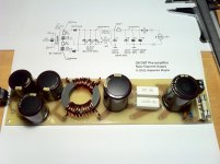
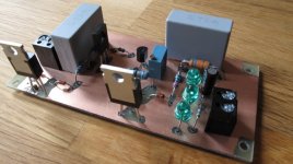
Slowly making some more progress on the supplies. Today I finished the two LT filament raw supply boards to deliver 18V with minimum ripple. Using PSU designer and recommendations from Rod Coleman, I came about with a circuit that delivers 18V and 30mV ripple at full load (1.05A).
I will stack the boards in the supply chassis to save some space. Now I need to work on the HT supply. That will be interesting!
BTW: I found that the noise I have was the HT bench supply. Will see what happens when I get my final HT.
Also did a THD test today and got THD=0.03% @ Vi=1Vrms and Vo=1.84Vrms with a CX-326... nice!
Cheers,
Ale
Attachments
Yes Felipe. You can get very clear instructions from Rod Coleman to design your raw power supply circuit to use Rod's boards. Mine have to be 18V as I'm using filament bias.
Have breadboarded the HT PSU with AZ1 and CLCLC smoothing stage succesfully. Now will crack on the Salas shunt regulator.
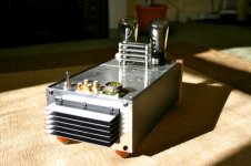
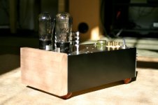
Also finished the pre-amp chassis with a nice wood touch. See attached....
Cheers,
Ale
Have breadboarded the HT PSU with AZ1 and CLCLC smoothing stage succesfully. Now will crack on the Salas shunt regulator.
Also finished the pre-amp chassis with a nice wood touch. See attached....
Cheers,
Ale
Attachments
Salas regulator will be on the supply chassis
Not the best solution IMHO. PS chassis should contain LV and HT raw supplies only.
Not at all, the Ll1660 use most of the space. Either way, I haven't built a complete separated chassis for LT and HT supplies. Salas regulator will be on the supply chassis
You have to modifie your Salas HV reg. for 4 wires Kelvin to avoid cable lenght.
You have to modifie your Salas HV reg. for 4 wires Kelvin to avoid cable lenght.
Why? And how? Can you please explain?
Salas shunt regulator board completed today. Tested and works nicely. Set output voltage about 170V with input of 200V. Ripple is below 10mV but probably is picked up by my oscilloscope leads in my noise workbench.
Now back to metal work and get the supply chassis done!
Now back to metal work and get the supply chassis done!
Attachments
Schematic four wires Kelvin for remote sense, link:
http://www.diyaudio.com/forums/power-supplies/134801-simplistic-mosfet-hv-shunt-regs-205.html#post2746868
http://www.diyaudio.com/forums/power-supplies/134801-simplistic-mosfet-hv-shunt-regs-205.html#post2746868
Last edited:
Tested today with a 50cm leads and couldn't see the difference in voltage drop/ripple. The shunt regulates fine, so will go with the original circuit. Also don't have space left in the chassis, so will be placed on the supply chassis. Will build as is and report results (hopefully soon)
cheers,
Ale
cheers,
Ale
this is my project now
source-DAC pcm58- nos--resistor- i/v converter
gain-#27
driver-#26
output-6c33 1w SE OTL cathode follower
Speaker Lowther EX4 in Hedlund horn
An externally hosted image should be here but it was not working when we last tested it.
An externally hosted image should be here but it was not working when we last tested it.
Que bello amplificador (what a beauty)!
I would love to see a schematic - can you post one?
Muchas gracias,
-- josé k.
Salas shunt regulator board completed today. Tested and works nicely. Set output voltage about 170V with input of 200V. Ripple is below 10mV but probably is picked up by my oscilloscope leads in my noise workbench.
Now back to metal work and get the supply chassis done!
I would say with 10mV ripple it is probably oscillating, what is the ripple going in after the prefilter ?
- Home
- Amplifiers
- Tubes / Valves
- #26 pre amp