Changing the subject slightly, I tried my 26 preamp with my 46 interstage 300b SET on stacked Quad 57 speakers last night at a friends. We compared this - my new system - with my older 10y transformer out preamp and my older 2a3 push pull amp (01A and 31 inputs), which he has. Both preamps are filament bias.
Results were heavily in favour of the new system, which was at times a religious experience - Schneiderhan playing the slow movement of Beethoven's Violin Concerto seemed to just float in the air. The 26 has a tonal beauty which I've never quite been able to capture with the 10Y much as I like that in other ways (plus it was cleaner in transformer out than with the capacitor coupling).
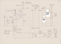
This 26 preamp is as my schematic posted a few pages back - two Hammond 156C plate chokes in series and Teflon FT-3 capacitor out. The only thing that took away from the listening experience - apart from the sound losing grip a little in congested passages which is the 300b SET - was, I think, the capacitor out. There was a slight but audible veil over the sound which was frustrating.
This listening experience leads me to believe that to get the best out of a 26 preamp it actually needs to be direct coupled to the first stage of the amp. You could do that with a stand-alone preamp, though it would only work with its partner amp, but the obvious thing to do is put the 26 stage in the amp. This would be a pain for most people with existing amps and preamps, though it's not difficult to construct. But having gone through this listening experience on very revealing speakers, that's the conclusion I came to. There are always many factors at work so it's hard to be conclusive with listening tests but I point the finger at the coupling cap. However good it is - and this was Teflon - the whole sound does go through this one capacitor and I'm sure it would be better if it didn't.
Andy
Results were heavily in favour of the new system, which was at times a religious experience - Schneiderhan playing the slow movement of Beethoven's Violin Concerto seemed to just float in the air. The 26 has a tonal beauty which I've never quite been able to capture with the 10Y much as I like that in other ways (plus it was cleaner in transformer out than with the capacitor coupling).
This 26 preamp is as my schematic posted a few pages back - two Hammond 156C plate chokes in series and Teflon FT-3 capacitor out. The only thing that took away from the listening experience - apart from the sound losing grip a little in congested passages which is the 300b SET - was, I think, the capacitor out. There was a slight but audible veil over the sound which was frustrating.
This listening experience leads me to believe that to get the best out of a 26 preamp it actually needs to be direct coupled to the first stage of the amp. You could do that with a stand-alone preamp, though it would only work with its partner amp, but the obvious thing to do is put the 26 stage in the amp. This would be a pain for most people with existing amps and preamps, though it's not difficult to construct. But having gone through this listening experience on very revealing speakers, that's the conclusion I came to. There are always many factors at work so it's hard to be conclusive with listening tests but I point the finger at the coupling cap. However good it is - and this was Teflon - the whole sound does go through this one capacitor and I'm sure it would be better if it didn't.
Andy
Hi Felipe,
1N4007 has large recovery-time, and makes big current-pulse noise (difficult to measure, easy to hear)
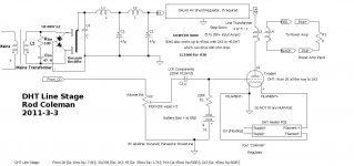
UF4007 Fairchild works really well, just add series-RC snubber across the secondary winding:
100-ohm 0,5W carbon composition and 22nF to 47nF 1500V FKP (LCR PC/HV/S best, or PAnasonic MKP 1000V).
No need for > 1A type!
As this schematic PSU part
Attachments
No Felipe, the suggested snubber components (R+C in series) are to be placed in parallel with the sec winding (Rod correctly stated "across the winding"), before the rectifier(s).
Thanks Massimo, You know what I meant!
.
Attachments

Thanks Massimo, You know what I meant!
.
Thanks Rod, please remember me suggested Tx values in V & A for the filaments heaters that I bought you.
Felipe, I replied about the Xfrm yesterday: 6V/5A (30VA), EI with split bobbins, not toroidal.
I got from Rod the same regs for #26 and I bought a pair of Hahn BV UI 396 0101 at Distrelec. They have a dual sec to be paralleled
Grazie Massimo, so 2 Tx one for each tube Rod filament, right?
Distrelec don't works in Spain, could I use this from RS:
Block | Transformadores | Transformadores | Transformadores para montaje en circuito impreso (PCB) | Encapsulado - Laminado, Serie FL (Salida Doble) |FL 30/6
Block | Transformadores | Transformadores | Transformadores para montaje en circuito impreso (PCB) | Encapsulado - Laminado, Serie FL (Salida Doble) |FL 30/6

As usual...... they write "Disponible en 48 horas" (available in 48 hrs) but when you try to order the item it suddenly become out of stock!
What about the smaller ones 201-7303 ?
These are out of stock till July 13.
201-7381 are in stock
")
Felipe, here's a good 6V/50VA:
PRO POWER|CTFCS50-6|TRANSFORMADOR, 50VA, 2 X 6V | Farnell España
I think Farnell ship with no cost.
PRO POWER|CTFCS50-6|TRANSFORMADOR, 50VA, 2 X 6V | Farnell España
I think Farnell ship with no cost.
Massimo, I believe it is right to delay HT. Also, a slow rise-time is helpful to prevent large turn-ON current pulses.
This question can cause many arguments! But I think the comments made by [ Hans van der Weyer [Philips thermionic tube division], about the risk of increased grid current, is the most powerful evidence.
http://www.chiark.greenend.org.uk/scopes/weyer.txt
This question can cause many arguments! But I think the comments made by [ Hans van der Weyer [Philips thermionic tube division], about the risk of increased grid current, is the most powerful evidence.
http://www.chiark.greenend.org.uk/scopes/weyer.txt
The problem: I can't delay the HT only, but the rectifier heaters too (as I don't have separate Xfrms). Thus the rectifier tube (#80) is still subject to cathode stripping.
OTOH, using just one switch, I power on some s.s. devices (your regs) that supply voltage (almost) immediately while the HT will follow after a while (the rectifier needs to warm up).
Another idea could be to use a relay driven by a NE555 that connect HT winding CT to gnd after few secs.
OTOH, using just one switch, I power on some s.s. devices (your regs) that supply voltage (almost) immediately while the HT will follow after a while (the rectifier needs to warm up).
Another idea could be to use a relay driven by a NE555 that connect HT winding CT to gnd after few secs.
- Home
- Amplifiers
- Tubes / Valves
- #26 pre amp