I tried searching and couldn't find any ref to measuring tube GM so I'm hoping this will be helpful.
I've got several 6BA6s that look like they are new. THis is the 'Cal tube' for the Mercury 1000/2000 Tube Test sets.
The tubes measure close to spec for Gm on my Mercury 1000 (which I recently calibrated). I'm trying to measure the tube Gm to verify the Mercury 1000 calibration.
I built a simple amp circuit using cathode bias (560 Ohm with 2u2 bypass), 4900 Ohm Plate resistor, 165V Plate supply, 1M grid resistor to gnd, 2nd and 3rd screens tied to plate. 2u2 Coupling cap on input from a signal generator.
The amp comes up with the plate voltage at 125V and cathode resistor drop of 4.5V for a bias current of roughly 8mA instead of the target 10mA. Close enough to start out with.
Problem is if I put a 3Vrms (1Khz) input, I only get an output of 15.2Vrms. With a load resistance of 4900 ohms this yields a Gm of 1034u-Mho. The tube is spec'd at 4300u-Mho.
I've calculated gain as Ip / Vi = (Vo / Rp) / Vi ....
With Cathode Bypass I was expecting to see the full gain of the tube. even though I'm 35V below the design spec on the tube.
Where am I going wrong?
Thanks.
Steven
Precisely.
I'm Trying to understand how to test a tube to the manufacturer's data sheet to verify Gm, In which case it becomes a reference tube.
The 6BA6 is spec'd at 4300-4400u-Mho. But, with what voltages? The data sheet (on nj7p) shows two sets of "Characteristics and Typical Operation" one at 250V Plate voltage and 11mA bias current (4400u-Mho), the second at 100V Plate voltage and 10.8mA bias (4300u-Mho). I assumed (yea, you know where that gets you) that I could set the tube up between the two and get near the same Gm since there was not much of a spread.
So why am I measuring only 1/4th what the spec is? Crank it up from 8ma to 11ma? Seems like that shouldn't make much difference.
I also tried a lm317 10 mA current source for cathode drive and it made little difference.
Steven
Hi Steven,
The formula for transconductance or Gm of a vacuum tube is as follows. Gm=delta Ia ÷ delta Vg. This is the difference in plate current divided by the difference in grid voltage that produced it. So in simpler terms it would be plate current divided by grid voltage. These terms are for RMS plate current & RMS grid voltage. Not DC values. Basically, a 1V signal that causes a 1 milliamp change in plate current is said to be a Gm of 1000.
DC plate current affects Gm much more then voltage, which only affects it to the extent that it can help determine current. It is also much easier to use even numbers in multiples of 10. In my large tube tester I use 1V RMS on the grid and measure RMS plate current across a 10 ohm resistor. Because I use much higher voltage, I have the 10 ohm resistor at the bottom of the plate supply just before ground. You will need a good RMS millivolt meter to make this reading. I use an HP 3400A but there are many other suitable types.
So as an example based on an AC Vg of 1, an AC plate current of 10 millivolts across 10 ohms would be a Gm of 1000, (referenced to a predetermined DC plate current). This could be scaled up accordingly to 100 millivolts across 100 ohms etc. Please note that on my system the plate PS is the plate load. No other load resister is used. For small signal tubes like yours a larger load resistor would be more useful, perhaps 1K or even 10K.
You will need a well filtered DC supply to avoid including hum in your measurment. For what you are doing, this should not be a problem. I would suggest that you provide some way of setting your tube under test to the required plate current. A bench supply with meters would be perfect. Perhaps keep us posted on your results.
Thanks.
I've been setting the input signal (1KHz) to 3vrms, and measuring the rms voltage at the plate with a 4K97 resistor for the plate resistor. I chose 1KHz as my input signal to avoid interference from 60/120hz ripple.
I used the rms plate voltage divided by the 4K97 resistance to determine the plate rms current, then divided it by the input rms voltage to get Gm.
I found the RCA tube spec to be more informative. I've changed to a separate bias supply for the grid(1), and tied grid 2 to a resistor divider to supply 100V to it. This made a big difference.
It looks like I need separate supplies for plate, grid(1), and Grid (2) to be able to adjust them to the spec in the book for each tube I test.
I'm up to around 3000u-Mho now from my initial 1000 u-Mho readings so I'm moving in the right direction.
Steven
Absolutly true !Hi Steven,
The formula for transconductance or Gm of a vacuum tube is as follows. Gm=delta Ia ÷ delta Vg. This is the difference in plate current divided by the difference in grid voltage that produced it. So in simpler terms it would be plate current divided by grid voltage. These terms are for RMS plate current & RMS grid voltage. Not DC values. Basically, a 1V signal that causes a 1 milliamp change in plate current is said to be a Gm of 1000.
Except you sould explicitly state "at constant plate voltage".
Steven, the deviation you noted is because you inserted a resistor in the plate circuit to measure the AC voltage accross it and this obviously means that plate voltage is no longer constant.
Use a very lo value for this resistor, as lo as your can regarding your meter sensitivity.
Yves.
A couple of other suggestions to get around the problem load resistor changing the plate voltage:
1)Use a milliameter and measure Ip directly while keeping Vp constant and varying Vg. Of course I realize that if you had a milliameter you probably would already be doing this, but I thought I would mention it.
2) Use a smallish load resistor by all means, but, you may not have any in the range of 1 ohm etc. So instead take measurements using 2 different load resistors of some reasonable size you do have, a few K or whatever. Use the same ac value of Vg both times. Call the first load resistor R1, and the second R2. Call the corresponding output ac voltages at those resistors V1 and V2. Then based on the equation V = Mu * Vg * Rl /(Rl + Rp) and the necessary algebra you get
Rp = R1*R2*(V2-V1)/(V1*R2 - V2*R1)
then Mu = V1 * (R1+ Rp)/(R1*Vg)
and finally Gm = Mu/Rp.
Now it can still be objected that Vp is not held constant. But this is the case in real circuits anyway, Vp is not constant, Ip varies, Gm and Rp vary. Thats reality. The best you can do is use a value estimated at the bias point. Gm, Mu and Rp are small signal concepts. Derivatives, tangents to curves at a point and all that. Dont worry about it when you build a circuit with 4900 ohms load and swing 15.2 volts across it that Gm doesnt match the spec sheet. You are now in the large signal world, Gm, Mu and Rp dont mean so much. Mu stays more level than the other two, use Mu and loadlines for these voltage levels.
I second that of course!
May be good to point that neither Gm nor Rp are constant, but variable according to plate current and voltage.
Fortunatly they move in opposite direction that's why their product (that is Mu) remains more stable.
Mu is also defined as the plate voltage variation for a grid voltage change at constant plate current.
On published plate curves Mu is the lenght of an horizontal (constant current) line between two grid curves while the slope/transconductance is the lenght of a vertical (constant voltage) line between grid curves.
Yves.
I built a simple amp circuit using cathode bias (560 Ohm with 2u2 bypass), 4900 Ohm Plate resistor, 165V Plate supply, 1M grid resistor to gnd, 2nd and 3rd screens tied to plate. 2u2 Coupling cap on input from a signal generator.
Steven
I did read this originally but forgot to comment on it. Yes, testing a 6BA6 as a triode instead of a pentode will lower the Gm value.
Problem is if I put a 3Vrms (1Khz) input, I only get an output of 15.2Vrms.
I'm thinking 3V RMS may be too high for this small tube. Three volts may be causing it to limit by going into partial cutoff. Perhaps looking at the waveform with a scope would verify this. I'd suggest no more then a IV signal.
I have actually measured the transconductance of 211 at varying grid and plate voltages (900V - 1100V) with good success using static dc measurements at several points along the characteristic curve of the device in question.
I found that you generally need to stay in the most linear portion of the curve and you need at least two points in that region as far apart as you can reasonably manage. The transconductance you measure is strongly affected as well by how big the difference in plate currents measured actually is, and by the current range over which you measure. (As you know transconductance is not a constant.)
I use precisely measured fixed grid bias (not cathode bias) and carefully measure the plate current at a known (and carefully measured) plate voltage for each known grid bias voltage. This provides pretty consistent results. This works for any tube, including your reference tube.
I use precision digital meters and avoid current sampling resistors when possible. With triodes you can usually measure current in the cathode circuit which at very high voltages is somewhat safer than measuring plate current directly in the plate circuit. With pentodes and tetrodes you have to measure the plate current and the comment about using a small current sampling resistor is relevant, although with static dc measurements as long as you measure the plate voltage as well you are usually all set. You should of course also measure the screen current and voltage. Bear in mind that the curves shown in a data book are generally the average of the measurements from a relatively large sample set. No tube you measure is going to have exactly the same transconductance as that based on the curves and data book specification - however it should generally be very close - with large sample sizes it may be possible to select a tube that closely matches the average, why you would want to is less clear..
Note that if you measure enough discrete dc op points (Vg vs Ip) at a given plate voltage you can generate very reasonable looking curves that match what you see in the data sheet somewhat closely with the caveat mentioned above. Because this is a slow process you generally can't replicate the curves into the area where dissipation ratings are exceeded except very briefly.
Calculate Delta Ip/Delta Vg per Hollowstate's remark in post #4
Don't put too many hours on your calibration reference tube as that will result in parametric changes (aging) that will ruin it as a calibration reference.
Last edited:
Thanks all. Lots to think about. I think my main errors were the triode connection and large plate resistance value.
I'm using a B&K 2534 scope and Fluke 8020B multimeter for measurements, not the best equipment, but they should be capable of 5% accuracy and should suffice initially.
Currently the test is just patched together on the workbench, but I plan on building a permanent test fixture once I get a prototype tested. When finished, I can take it in to work where I have access to properly calibrated and certified precision equipment to do final calibration and verification on the test set..
1. I've switched from the triode configuration to pentode per the RCA data sheet, with separate screen supplies, grid bias supply, etc so I am no longer testing with cathode bias.
2. I've eliminated the 4K79 plate resistor, and am using a 1 ohm resistor in it's place ( actually two 4R7 resistors for 9R4, which I will verify on a precision resistance meter when I get a chance or get a true 1 ohm resistor.
3. I've reduced the input from 3Vrms to 1Vrms, and can go lower if necessary.
4. I've got 9 tubes to play with. Six look like they may be NOS that I'll hold back for once I think the test set is working right. (These six tubes are clean and look new with no emission discolorization on the glass at plate openings)
Since the oscilloscope can measure RMS values, I am biased towards using it for both the input and output measurements. Since both the Vin and Vout measurements are made with it, and it's tolerance should be consistent for both measurements, dividing one by the other nulls out the error, no?
I've tried measuring AC Current with the Fluke but only get two digits of resolution.
Based on this I am thinking of using an AD629 diff amp ( good to +/-500V Common mode) to buffer the voltage across the 1 Ohm resistor, then feed it into two or three successive gain of 10 stages. Two stages should give me 100mV/mA which can be easily measured on the oscilloscope. Three stages would scale nicely as it would yield 1000u-Mho scaling, but I'm not sure how much distortion I'll get that way. I may have to just try it. I'm thinking of using TL072 or TL074s for the gain stages since I'm dealing with millivolts and not microvolts so these should be fine. (Since I'm only interested in the 1KHz ac signal, there should be no issues with offset or input bias issues as long as I watch my resistor values)
Does this approach sound reasonable?
My goal is not to find a tube with the factory spec 4300/4400u-Mho gm, but rather to be able to measure Gm accurately on a tube to use it to verify the calibration of my tube tester.
Steven
Last edited:
Proposed Test Set
Hopefully this will work. Attached schematic is proposed test set for measuring 6BA6 Gm. Adjust plate voltage to 100V, adjust screen voltage to 100V, adjust cathode current to 10.8mA, repete until stabil values are achieved. apply a 1vrms 1KHz input signal to grid. Measure voltage (Vrms 1KHz) across 1.00 Ohm resistor to get cathode current. Calculate Gm as Cathode current/Input voltage.
Optional Diff amp and Op amps may be added to scale signal if I have trouble measuring mV signals with my scope.
NOTE: 68 Ohm resistor is called out in GE data book wrt tube Gm so I left it in instead of connecting cathode directly to ground.
An externally hosted image should be here but it was not working when we last tested it.
Hopefully this will work. Attached schematic is proposed test set for measuring 6BA6 Gm.
Looks like a good setup. Measuring voltage across that 1 ohm resistor may prove difficult even with a direct 1:1 probe. Some form of isolation may be required as the resistor is elevated 100V above ground. You might be able to put it at the bottom of the cathode resistor. There should be virtually no grid or screen current drawn to affect the outcome. And if the level is too low, perhaps substitute a 56 and 10 ohm resistor in series for the 68 ohm. Or use a 10 ohm at the bottom of the plate supply as I do.
You say your B&K 2534 scope can measure RMS. I'm not very familiar with this model. I do know it has some special functions. Can I assume it has a function to automatically do the conversion from peak-to-peak (as it normally reads) to RMS? (RMS=P-P x 0.3535)
Last edited:
The B&K is nice. Not as good as a Tektronix, but at about 60% the cost it was a good deal. It can do math including - + X and FFT, but not division.
Another possibility would be to wind a small toroid transformer with say a 1:10 or even greater turns ratio, then measure the output of it with the scope on 10X so I don't load it down.
The VR tubes should help stabilize the voltages.
Another possibility would be to wind a small toroid transformer with say a 1:10 or even greater turns ratio, then measure the output of it with the scope on 10X so I don't load it down.
The VR tubes should help stabilize the voltages.
In a pentode you should probably measure in the plate circuit because the cathode current is the sum of the plate and screen currents. I am not sure you can assume that the screen current has only a dc component, and if that is not the case then the combination of the currents will result in an error in your measurement. I have not measured the transconductance of a pentode with a home brew jig so I cannot say for certain that this is or isn't going to be an issue. Just a thought..
I think I finally got the breadboard working.
I had to add 200uf bypass caps to the screen (at screen) and plate supplies (above 0.94 Ohm Resistor, not at plate).
It takes two iterations of adjustments to get it stable.
1. adjust plate voltage
2. adjust screen voltage
3. adjust grid voltage for 0.734V across cathode resistor (68Ohm) for 10.8mA cathode current.
4. Adjust signal generator for 1.04Vrms in
Repeat steps 1-3
Measure ac plate signal. For two used tubes and one apparently new tube I got:
Vout Vin calculated Gm
36mV 10.4Vrms 3683 Used Tube
38mV 10.4Vrms 3887 Used Tube
44mV 10.4Vrms 4500 New Tube?
An externally hosted image should be here but it was not working when we last tested it.
I had to add 200uf bypass caps to the screen (at screen) and plate supplies (above 0.94 Ohm Resistor, not at plate).
It takes two iterations of adjustments to get it stable.
1. adjust plate voltage
2. adjust screen voltage
3. adjust grid voltage for 0.734V across cathode resistor (68Ohm) for 10.8mA cathode current.
4. Adjust signal generator for 1.04Vrms in
Repeat steps 1-3
Measure ac plate signal. For two used tubes and one apparently new tube I got:
Vout Vin calculated Gm
36mV 10.4Vrms 3683 Used Tube
38mV 10.4Vrms 3887 Used Tube
44mV 10.4Vrms 4500 New Tube?
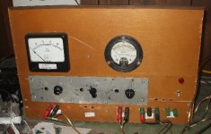
This is the set up I use. Having independant regulated plate and screen voltages makes things simpler, but more expensive. I made the power supply shown using parts I had already, and put it in a wooden box to keep cost down. If I had to buy parts I would never have done it.
But once you have independant plate and screen supplies, and a grid supply, then you can take the approach mentioned by kevinkr, ie just measure a boatload of dc points, and use the data acquired for any number of things, calculating Gm, drawing plate curves, build SPICE models, whatever.
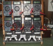
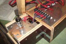
The tester shown is 8 inexpensive meters stuck to a panel with velcro and wired up to terminal blocks and switches. I have tube sockets of various sizes on plates that I hook up to it, socket wiring colour coded as to pin number, and test set terminal block labeled as to voltage function, so I can test any tube.
Of course it can also be used to power, and meter, other projects.
OK, so the picture upload doesnt work the way it used to , I will figure out what to do , and post pictures later.
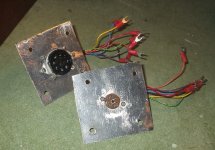
I found the "Manage Attachments" button, so here are the pictures.
But once you have independant plate and screen supplies, and a grid supply, then you can take the approach mentioned by kevinkr, ie just measure a boatload of dc points, and use the data acquired for any number of things, calculating Gm, drawing plate curves, build SPICE models, whatever.
The tester shown is 8 inexpensive meters stuck to a panel with velcro and wired up to terminal blocks and switches. I have tube sockets of various sizes on plates that I hook up to it, socket wiring colour coded as to pin number, and test set terminal block labeled as to voltage function, so I can test any tube.
Of course it can also be used to power, and meter, other projects.
OK, so the picture upload doesnt work the way it used to
, I will figure out what to do , and post pictures later.I found the "Manage Attachments" button, so here are the pictures.
Attachments
Last edited:
The test set is coming along pretty well. I've managed to make it with bits and pieces on hand including an old aluminum chassis, transformer (ended up doing a voltage tippler to get the right B+), etc. I even found a 1 Ohm 0.1% resistor to use for current sensing.
I added a 1KHz oscillator, and attempted an active full wave rectifier, but wasn't happy with the results so the output currently is ac with a scale of 1vrms/1000 u-Mho. Simple meter reading will give the results. I'll verify it with the scope before I trust the meter reading.
I added a 1KHz oscillator, and attempted an active full wave rectifier, but wasn't happy with the results so the output currently is ac with a scale of 1vrms/1000 u-Mho. Simple meter reading will give the results. I'll verify it with the scope before I trust the meter reading.
An externally hosted image should be here but it was not working when we last tested it.
Last edited:
Finished Test Set,
And blew it up.
It turns out the rotary switch I chose to select Vp, Vs, Vk, Vg, and amplified output voltage had insufficient isolation between segments when switching. The loud arcing noise and stuck switch were a good indicator something was wrong. I blew the op amp and will have to completely disassemble it to replace the part.
I've found a ceramic disk rotary switch from a Tektronix plug in module that looks like it will work if I can get it to fit (it is larger than the original).
Oh well, I'm still on disability for another two weeks with nothing better to do....
Your problem with the switch may not be insulation. Switching live DC is problematic due to the arcing problem. Once an arc starts, it can go to ground or any nearby contact since the air around the arc becomes ionized and conducting. There are no zero crossings to extinguish the arc, as there are with AC. the 70 volt DC from my solar panels will draw an arc up to 1/2 inch long. If you have a high current capacity e.g. a filter cap, there can be quite a lot of energy in the arc. For the same reason, AC rated fuses are practically useless for DC.
I think the best solution is to not switch live DC.
- Status
- This old topic is closed. If you want to reopen this topic, contact a moderator using the "Report Post" button.
- Home
- Amplifiers
- Tubes / Valves
- Measuring Tube Gm