I suspect something less than 100K might suffice. One of the potential concerns with a resistor and doing an ac based gm measurement except at very low frequencies might be the effect of the meter's input capacitance - you could compensate of course with the appropriately sized capacitor across your current limiting resistor. And yes you would need to compensate for the effect of the resistive voltage drop. The other option would be just to get a couple more inexpensive meters and not switch things at all.
It may be easier to measure the cathode current separately from the rest of the measurements, since this is specified in the RCA data sheet and needs to be set. I'm setting the cathode current by adjusting the grid bias, then adjusting the plate and screen voltages.
I rebuilt the amp sections, and took readings on 13 tubes.
I measured the voltage drop across the cathode resistor (68 Ohm) to set the cathode current by adjusting the grid bias. Once it was set to .734V +/-0.5%, I adjusted the plate and screen voltages to 100V +/- 0.5%. 0.5% is about as good as I can get with single turn pots for adjustments.
I also measured the tubes on the Mercury 1000 for comparison.
The Gm varied from 2670 to 5333 on my test set, and 2000 to 4200 on the Mercury.
# Test Set V-Grid Mercury
1 2670 -1.34 2000
2 2700 -1.74 3950
3 2700 -1.66 3900
4 3060 -1.42 3950
5 3130 -1.75 3250
6 3250 -1.81 2600
7 3250 -1.41 3900
8 3250 -1.29 4100
9 3360 -1.25 4150
10 3360 -1.29 4350
11 3360 -1.16 4100
12 3480 -1.05 3350
13 5333 +0.10 4200
#s 5,6,12, and 13 are interesting as they don't follow the main trend.
5 and 6 show a decrease in grid voltage to achieve the same cathode current, with a drop in Gm on the Mercury test set.
12 shows a drop in gm on the mercury, with an increase on the test set.
13 shows a major jump in Gm on the test set, and the highest Gm on the Mercury. It also is the only tube requiring positive grid voltage to achieve 10.8mA of cathode current.
I presume the +21-44% difference between the test set and Mercury is due to the differences in the way they measure Gm, although I expected to see a better correlation.
These tubes are of unknown status as they came from a TV repair shop that didn't keep track of which tubes were used and which were new. I suspect most if not all are used.
I've purchased 10 NOS 5749W/6BA6Ws. Once they come in, I'll try to see if I can get more consistent results.
How dependent is Gm with respect to the AC screen drive voltage?
The definition simply states a change in plate current with respect to a change in grid voltage with the plate voltage held constant, and RCA RC-30 seems to imply that a 1V signal should be used (P103, Fig. 131).
I was testing with a 1V-rms input because it was easy to measure the change in output current, but I tried a 0.1V rms and now a .01Vrms input and I see a marked difference in readings. As I decrease the input voltage, I see an increase in Gm.
By the time I get to 0.01Vrms I am seeing a Gm in the 4000 range compared to 3200 at 1Vrms input and 3400 at .01Vrms.
This is more in line with what I expect from the tubes I have, and once I calibrated the Mercury 1000 based on these readings, the 12 KT88s a friend asked me to test all dropped the range I expected. They were reading 18% low before I re-calibrated the Mercury 1000 based on the latest test data on the 6BA6s.
Steven
Last edited:
I hope this was just a late night typo. Dynamic Gm testing is traditionally done with a signal on the control grid (G1), not the screen. And a 1 volt signal level seems to be the accepted standard. Although I suppose a 0.1 volt level could be used as well, or for very sensitive small signal tubes.How dependent is Gm with respect to the AC screen drive voltage?
As the input level goes down, the accurate measurment of shrinking AC plate currents can become more challenging. Effective shielding along with a good common ground between instruments is necessary. Sometimes noise and stray pickup will affect readings. I think you're using op-amps in your measurements somewhere. Small offset currents that weren't noticeable at higher levels may be affecting things at very low levels. Perhaps even thermal noise in the tubes may play a part at these low magnitudes.
Yes, late nite working and fat thumbing it got screen instead of grid.
Yes, AD629 Instrumentation amp followed by two gain stages to measure the current through the sense resistor.
Since I'm interested in the 1KHz test signal and taking AC measurements, I would not expect offset to be an issue. I did null the op-amps to get less than 10mv offset just to be sure I was not driving any stage to clipping.
With 1Vrms Input, I was concerned that I might be pushing the tube out of linear operation. Although, 1Vrms and Gm of 4100 should put the excursions around +/-5.8mA. With a bias point of 10.8mA that should remain in the linear range.
I picked up a new meter today at Radio Shack (22-812). I'll compare the results with it to what I get with my other meter. Also this meter has a low scale of 400uA, so I might just put it in the cathode circuit and directly measure ac current with it to see if I get a better measurement that way.
Well, I'm still getting readings that I believe are 20-25% low.
I believe the readings are low because I can use the measured tubes to calibrate the Mercury 1000 test set, and then when I test new tubes, I get readings that are consistently 20-25% below what I expect.
Therefore I must be doing something wrong in trying to measure Gm of the 6BA6s. The Screen and Plate supplies are regulated with 0B3s to around 108V, then followed by 5K pots with 220uF caps as final filters to set the actual screen and plate voltages.
I placed the new meter connections in the plate drive (cap is on the supply side of the meter, not at the plate). My procedure is :
1. Set filament voltage to 6.3Vac
2. adjust grid voltage to achieve a plate current of 10.8mA (new meter directly in plate circuit measuring DC Current).
3. Adjust screen and plate voltages to 100.0VDc
4. Re-Adjust screen voltage to get plate current back to 10.8mAdc if it has shifted
5. Verify screen and plate voltages haven't shifted, repeat 3-5 as necessary.
6. Verify 1KHz grid drive is 1.00V (this changes from tube to tube, so my drive impedance is probably too low, but can be adjusted)
7. Switch meter in plate circuit from DC to AC and measure plate current
8. since grid drive is 1vrms, plate current in mA rms represents Gm.
I've replaced all the electrolytic caps, and a few power resistors that were out of tolerance in the test set.
Steven
I believe my mistake was a misinterpretation of the data sheet.
The data sheet under "Characteristics" calls out two configurations. One at 100V Plate and one at 250V Plate. I'm using the 100V Plate specs which are :
Plate Voltage - 100V
Grid-No3 and internal shield - Connected to cathode at socket
Grid-No2 supply voltage - 100V
Cathode Bias Resistor - 68 Ohm
Plate Resistance, approximately - 0.25 Meg
Transconductance - 4300 umhos
Plate Current - 10.8 mA
Grid-No2 Current - 4.4 mA
Grid-No1 voltage (approx) for transconductance of 40 umhos - --20Volts
Since I am adjusting the Grid-No1 bias to set the plate current to 10.8mA, I should not have had a cathode resistor in the circuit. The cathode resistor was providing negative feedback which resulted in low measured Gm values.
Steven
Having removed the offending cathode resistor you should be getting correlation within a few % or better of the published numbers which were usually based on the averaged measurements of a large number of samples.
Sounds like quite a worthwhile project and with what you are learning you will be able to determine the transconductance of just about anything out there under realistic operating conditions.
Sounds like quite a worthwhile project and with what you are learning you will be able to determine the transconductance of just about anything out there under realistic operating conditions.
I got lucky and my 10 JAN5749Ws arrived this morning. The seller actually sent me 12 tubes, which was fortunate since two had very low Gm.
I suspect the JAN5749W is a heavy duty version of the 6BA6, and has lower GM overall based on this sample (that or I got un-lucky).
I compared the Gm measured with my test set and the results from my Mercury and got the following (first number is my test set, second number is Mercury):
3270 - 4150 26.9%
3620 - 3600 -0.5%
3750 - 3600 -4.0%
3760 - 4250 -13.0%
3840 - 3700 3.6%
3850 - 3900 -1.29%
3870 - 3500 -8.2%
3800 - 3880 2.06%
3910 - 4200 7.42%
3910 - 4250 8.69%
3950 - 4000 1.27%
4020 - 3950 -1.74%
1, 4, 6, 7 (possibly 9) and 10 seem to have a lot of variation. I suspect this is due to the difference in test methods between standard Gm testing and the way the Mercury tests tubes (more generic).
I guess I could do an Excel spreadsheet and come up with a better cal point that would even out the spread, but it's too late at night for that.
In fact that might be a better way to calibrate the test set.
I guess one of the things I am wondering is under what conditions is the Mercury actually testing your tubes?
Your test jig is a whole lot more rigorous and I suspect that the mercury is using dropping resistors to drive the screen and that the screen current in some devices may be a bit higher or lower than the mercury expects and hence the different readings.
You might actually want to measure screen current on your jig and observe whether the ones that correlate best with the Mercury also happen to all have very similar screen currents whilst the ones that don't differ significantly. Just a thought..
Yes, I didn't consider the screen other than setting the voltage to 100.0V.
I've come to the conclusion that the chassis I chose for my test set is too small considering the changes I've made. I'm going to start over with a larger chassis, and include a set of SIMPSON 135-0-0-13-0 LCD meters to display DC Plate Voltage, DC Plate current, AC Plate Current(with a 1vrms input =Gm), DC Screen Voltage, DC Screen Current, and DC Grid Voltage.
I'm also going to rework the Plate and Screen supplies to allow me greater adjustment latitude and current capacity in testing so the test set will be more generic. I'll ditch the 0B3s in favor of fuylly regulated supplies (FET pass transistors probably).
Not exactly what I started out to do, but I think it will pay off in the end.
Reading your interesting journey I made two observations.
- tubes in their circuits will oscillate, though conditions under which this manifests may vary. Did you take precautions like a grid stopper etc?
- seems you did not make use of the stabilisation of your G2 supply. When a tube under test oscillates, it may develop G2 current which in turn will drop the G2 supply voltage over the 5K pot you used. As you probably know the penthode is very susceptible to changes of the G2 voltage, more than small changes to the actual plate voltage (!).
Readings in the 1940/50s were made with 10Kohm equipment, from what I usually see in old Philips publications. Modern SS equipment has higher impedance so test outcome may vary somewhat.
Last edited:
Yes, I didn't consider the screen other than setting the voltage to 100.0V.
I've come to the conclusion that the chassis I chose for my test set is too small considering the changes I've made. I'm going to start over with a larger chassis, and include a set of SIMPSON 135-0-0-13-0 LCD meters to display DC Plate Voltage, DC Plate current, AC Plate Current(with a 1vrms input =Gm), DC Screen Voltage, DC Screen Current, and DC Grid Voltage.
I'm also going to rework the Plate and Screen supplies to allow me greater adjustment latitude and current capacity in testing so the test set will be more generic. I'll ditch the 0B3s in favor of fuylly regulated supplies (FET pass transistors probably).
Not exactly what I started out to do, but I think it will pay off in the end.
While you're rethinking...
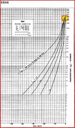
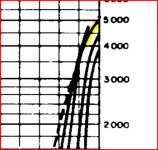
I attached the 6BA6 gm curve for reference. I think the measurement needs to be done in the area of the chart I highlighted in the enargement. To measure gm between 4000 and 5000 the grid swing needs to be <= 1.5V peak-peak (~0.5 VRMS) or less and biased up so that Vg1=0 on the positive peak. I think for small signal pentodes the 0.1V RMS might be a better choice if you can get the S/N ratio of the test set good enough. Your current 1VRMS produces too much current swing at the anode.
Michael
Attachments
I had suspected that and tried lower drive levels.
Thanks for the attachments.
Right now I'm working on better regulation of the plate and screen supplies. I've got an FET based current source working up to 180V (with an appropriate heat sink it should be good to 400V, or better with a different FET). This with the 100V minimum output (drive for the Plate and screen) should allow me to control the supplies from 100 to 350V with a 400V supply input. I plan on using this with a variable resistor to ground to set the output voltage. an Op Amp for a sense amp and another FET for the pass transistor should do it. Big Heat Sinks will be required. Say 75mA with a drop of 250V just to play it safe means 18.75W dissipation. 0.4 W/K with a temp rise of 50C looks like it will be close for the IRF7222/723 which should handle 20W. I may have to find another FET if I cook any of the IRF722/3s.
Did I mention I need a bigger chassis?
Man, I wish I hadn't passed up on the sloped panel test sets that were scraped at work last year. The guts were useless, but those cabinets would have been great. Oh well.
Steven
An externally hosted image should be here but it was not working when we last tested it.
Hi everyone,
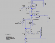
I'm trying to adapt my curve tracer to also measure transconductance using an externally 100mV 1KHz feed. As I'm also using a digital panel meter to switch between anode, screen and grid voltage measurement and avoid impacting the grid bias due to the meter input impedance, I changed a simple bias circuit to a simulated inductance (gyrator) to provide a stable DC bias point. That's works (simulates fine).
Now, when I'm adding a gyrator load and placing a 10 ohm sensing resistor in the anode to measure GM using an AC mV panel, when I simulate it in LTSPICE I get very tinny signal close to 15uV
Am I making a basic mistake here?
Thanks
Ale
Attachments
Yes, it's works, but...
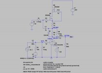
1.) If your negative bias supply (gyrator) not ideal, it makes as divider.
Divider with 1Meg resistor (DC), and divider with signal generator, then shunt input signal.
2.) I think anode current (variation) is to small to measuring in 10R, without amplifying.
p.s:
add this spice directive to sim:
.MEAS TRAN Output RMS (V(Meter2)-V(Meter1)) TRIG time=20*period TARG time=40*period
- Status
- This old topic is closed. If you want to reopen this topic, contact a moderator using the "Report Post" button.
- Home
- Amplifiers
- Tubes / Valves
- Measuring Tube Gm