I'm trying out various types of CF's and have started with this simple design.
I am having trouble understanding why I have such a low voltage on the grid (24V). I understand I need a 6 volt difference between cathode and grid, for a CD players 2 V input (6 volt swing). I could use 3 leds for the cathode resistor I guess.
I have tried adjusting the resistor values but have had no luck. I tried MJ's example but had only 8 volts on the grid
Your advice would be greatly appreciated.
Strangely it sounds quite good as I tried it through some test speakers.
Attachments
I understand I need a 6 volt difference between cathode and grid, for a CD players 2 V input (6 volt swing).
Nope. There's your misunderstanding. You need roughly 6V/mu. Remember, the cathode follows the grid.
Hi SY,
Maybe these explanations threw me off the track:
From the Valve wizard:
http://www.freewebs.com/valvewizard/accf.html
it's showing 140 Volts on the cathode and 136 on the grid.
Am I missing something?
Maybe these explanations threw me off the track:
Remembering that the quiescent voltage shown on the load line actually indicates the anode to cathode voltage, the actual quiescent voltage on the cathode is therefore equal to the HT - Vak. An easy way to read off the true cathode voltage quickly is to add a reversed voltage scale to the graph, whose '0V' point corresponds to the HT. In this case the load line indicates that the voltage across the valve is 140V. The cathode voltage must therefore be HT-Vak = 280-140 = 140V. The grid voltage must be 140+(-3.4) = 136.6V
From the Valve wizard:
http://www.freewebs.com/valvewizard/accf.html
it's showing 140 Volts on the cathode and 136 on the grid.
Am I missing something?
Your numbers, at least on the schematic do not add up.
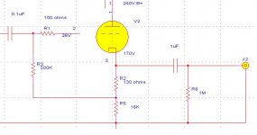
I'll go by the schematic as I am not sure what the rest of your post means. The voltage on the cathode is 170V, divided by the cathode resistor 16kohms gives a cathode current of 10mA. That all sounds correct. Now multiply the 130 ohm bias resistor by the cathode current to give you the voltage drop across it which is about 1.4V. That is your bias voltage. R2 is your bias resistor and you will need to adjust it to get your proper current through the tube.
I'll go by the schematic as I am not sure what the rest of your post means. The voltage on the cathode is 170V, divided by the cathode resistor 16kohms gives a cathode current of 10mA. That all sounds correct. Now multiply the 130 ohm bias resistor by the cathode current to give you the voltage drop across it which is about 1.4V. That is your bias voltage. R2 is your bias resistor and you will need to adjust it to get your proper current through the tube.
Brit01 said:
6V would mean having 600 ohm bias resistor if current remains at 10ma.
if you look at your measurements you have 170 volts at the cathode. That is the voltage you need to use to calculate the current through R2 & R5. The 6V number is the delta between your cathode and grid (and is your bias voltage) although yours is much lower in this circuit.
hope that helps
Still confused about how much bias voltage I need for a CF.
I thought it was about 6V but not sure after SY's comments.
6V would mean having 600 ohm bias resistor if current remains at 10ma.
If you change the bias resistor to a different value the current will change too. That's the bias resistor's job: it adjusts the current going through the tube.
If you increase the bias resistor to increase head room, the tube will draw less current. If you need more current, then increase the B+, but you will have to adjust the bias resistor again.
I don't really understand if you have built this or not, but my suggestion is to use a 500ohm pot (make it at least 1W) as a bias resistor and put a 200 ohm resistor between the pot and the load resistor so that there is always some V on the grid. Vary the pot and measure the current.
Brit01 said:I am having trouble understanding why I have such a low voltage on the grid (24V).
I suspect it is because you are trying to measure the voltage between grid and ground. The grid is bootstrapped; its impedance is so high that your volt meter will 'drag down' the voltage, giving you a false reading. If you measure the voltage directly across R2 you should find it is closer to 6V (or whatever).
I suspect it is because you are trying to measure the voltage between grid and ground. The grid is bootstrapped; its impedance is so high that your volt meter will 'drag down' the voltage, giving you a false reading. If you measure the voltage directly across R2 you should find it is closer to 6V (or whatever).
Interesting. Yes I was measuring to ground.
Ok I will measure on both sides of the resistor.
btw, I changed to a 6N1P last night and adjusted the values to see the effects.
I have reduced the cathode resistor to 10K.
I am reading 104 Volts on the cathode and about 102V at the junction of R5.
10mA so drop is about 1.1 V.
I will measure R2 tonight (not to ground).
Thks very much.
By the way what would be the sonic advantages of taking off the bootstrap with cathode straight to ground and a divider of 1M from B+ to grid. I see that is another method of CF.
I also want to experiment with another triode used as a CCS. Is there really an audible difference using this method?
Brit01 said:
. . .
By the way what would be the sonic advantages of taking off the bootstrap with cathode straight to ground and a divider of 1M from B+ to grid. I see that is another method of CF.
I also want to experiment with another triode used as a CCS. Is there really an audible difference using this method?
Sonic and audible "differences" are numerous !
At first, the bootstrap effect drastically increases the input impedance so that, for a given low frequency attenuation, you can use a lower value for the input capacitor.
Consequently, the perceding stage (or whatever you tie into) enjoys for less loading and this can change its behaviour.
The divider method tend to reinject some noise from the power supply into the grid, not really wanted !
But you may unnotice that if sufficiently smoothed !
A CCS in place of the bottom cathode resistor is like having an horizontal load line and improves the linearity ... unless you have an external load, wich is almost always the case because it is the "raison d'être" of such a stage:
-Minimal load for the source
-Maximal current to the load
Experiment, check and enjoy yourself but find a better multimeter

Obviously, yours has a too low internal resistance, that's why it "pulls" grid voltage down.
A trick to check your multimeter:
You must read the same value when switching from a range to another, eg 300V full scale and 1000V full scale.
Yves.
Experiment, check and enjoy yourself but find a better multimeter
yes I have a real cheapo
Thanks very much for the explanations. I will continue experimenting, this is part of the fun isn't it?
But I must get some of these designs in some nice chassis.
Brit,
>>Still confused about how much bias voltage I need for a CF.
I thought it was about 6V but not sure after SY's comments<<
This data does NOT apply for a cathode follower. It is possibly true for a normal common cathode gain stage, but with a cathode follower, the cathode FOLLOWS the grid, and hence you don't get "cut off" situations as you would with a common cathode stage and inadequate grid/cathode V - as long as the **cathode** is high enough above gnd.
But you could make a horribly badly designed Cf and have the cathode at (say) only 2V above ground, and then of course it can't swing enough to follow a CD player signal. I have seen exactly this is a tube output Chinese CD player - HORRIBLE 2nd harmonic distortion - yet some people defended it's sound when I critiqued it!
Regards, Allen (Vacuum State)
Allen Wright said:
. . .
I have seen exactly this is a tube output Chinese CD player - HORRIBLE 2nd harmonic distortion - yet some people defended it's sound when I critiqued it!
Regards, Allen (Vacuum State)
That's tube's sound

- Status
- This old topic is closed. If you want to reopen this topic, contact a moderator using the "Report Post" button.
- Home
- Amplifiers
- Tubes / Valves
- Cathode Follower confusion