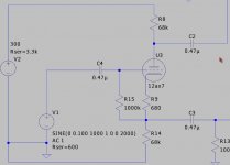
Hi all, I've been trying to simulate a phase splitter in LTSpice, and puts the cathode and anode signals in phase? Ie it's not acting like a phase splitter at all.....
Voltages are all reasonable and expected.
Has anyone heard of anything like this before?
I was thinking maybe an absolute value taken in the subcircuit or something?
Here's the model I'm using:
.subckt 12ax7 P G K
Bp P K I=((0.001149607902m)+(0.0001063352726m)*V(G,K))*uramp((91.16514401)*V(G,K)+V(P,K)+(52.29904339))**1.5 * V(P,K)/(V(P,K)+(2.177964467))
Cgp G P 1.7pF
Cgk G K 1.6pF
Cpk P K 0.46pF
.ends 12ax7
I thought this was inherently impossible?
Attachments
Might be a problem with your triode model... Or something else.
Note I did as you did wrt to the non-inverting output, but normally I would take the signal directly from the cathode as doing it your way results in a significant amplitude error.
Note I did as you did wrt to the non-inverting output, but normally I would take the signal directly from the cathode as doing it your way results in a significant amplitude error.
Attachments
Only thing I can think of is that you have a model written in a possibly incompatible version of spice.
I have included the symbol library and tube libraries I used, they are a compendium of models from Duncan Monroe and other sources. (Versions are demonstrably compatible with this version of spice or I have made them so as required.)
These models will run in LTspiceIII and LTspiceIV with no changes being required.
You probably know all of this already, but navigate to C:/Program Files/LTC/LTspiceIV/lib then -
Place the tube.lib file in your "sub" folder (rename, archive or delete the original)
Place the entire "Tubes" folder in your "sym" folder. (rename, archive or delete the original as necessary)
You will find you have lots of models arranged by triode/tetrode/pentode/diode and they generally work well. (Some DHT models are a bit quirky wrt to cathode/filament behavior, IIRC the 50 model specifically.)
Archive should unzip ok, I deliberately choose a non linux archive format.. (I run linux)
Attachments
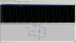
I have used that "style" of model in LTSpice many times. I copied the model and used it in a Cathodyne splitter circuit and it works fine.
Where did you take the output voltages from ? If you go from output to ground in each case they will be out of phase as they should be.
But if you got the outputs by for example putting the red probe on the top of plate resistor and the black on the bottom of the plate resistor, and the other output by putting the red probe on the top of the cathode resistor and the black probe on the bottom of the cathode resistor, then those voltages will be in phase.
Robert McLean said:I have used that "style" of model in LTSpice many times. I copied the model and used it in a Cathodyne splitter circuit and it works fine.
Where did you take the output voltages from ? If you go from output to ground in each case they will be out of phase as they should be.
But if you got the outputs by for example putting the red probe on the top of plate resistor and the black on the bottom of the plate resistor, and the other output by putting the red probe on the top of the cathode resistor and the black probe on the bottom of the cathode resistor, then those voltages will be in phase.
I am pretty familiar with LTspice (use it nearly every day) and am confused by your reference to red and black probes in Linear Tech LTspice, as far as I know all voltage measurements are always referenced to ground (circuit common) and there is only a single blue voltage probe present in any version I have ever used. Current measurements are made by right clicking the circuit node where you want to measure the current. The currents are in phase in the cathode and plate circuits obviously.
Not all spice model formats are compatible with LTspice although I have found that 3FS generally is. Also many newer tube capture programs generate spice models in LTspice format. Translation is generally easy if required. (And you'll know it is required when LTspice can't find the model or generates various error messages about the model you are using.)
Kevin
I am currently using version LTSpice IV, version 4.01g, but have been using it for many years and as far as I can recall there has always been the red and black probes. If you run a simulation, then hover the probe over a point on the schematic the probe is red. If you then left click and hold the mouse button down the probe turns black and you can move to a second point and release the mouse button. You will then measure the differential voltage between the two points. Thus you are not restricted to voltages referenced to ground. Equivalent to adding a trace and putting in for example V(node1,node2) using the Add Trace menu.
I thought perhaps this is what the original poster had done, and had inadvertently mixed up the phases.
Robert McLean said:Kevin
I am currently using version LTSpice IV, version 4.01g, but have been using it for many years and as far as I can recall there has always been the red and black probes. If you run a simulation, then hover the probe over a point on the schematic the probe is red. If you then left click and hold the mouse button down the probe turns black and you can move to a second point and release the mouse button. You will then measure the differential voltage between the two points. Thus you are not restricted to voltages referenced to ground. Equivalent to adding a trace and putting in for example V(node1,node2) using the Add Trace menu.
I thought perhaps this is what the original poster had done, and had inadvertently mixed up the phases.
Learn something new everyday, I'll give that a shot next time I am working in LTspice - I too have been using it for years, but seem to have missed this feature somehow.
Edit: Just tried it and all I can say is "groovy" 😀 Thanks for the tip...
I'm running LTspiceIV 4.03H in Wine 1.0.1 under 64 bit Ubuntu Linux 9.04 and other than CTRL-R and CTRL-E not working as expected it runs great. (I also run Windows XP upon occasion, but less and less.)
- Status
- Not open for further replies.
- Home
- Amplifiers
- Tubes / Valves
- Cathodyne Phase splitter simulation problem?