Hi. I have some questions about interstage transformer and tube interaction. I have been searching around but have not found the information I need.
It seems the interstage transformer replaces the plate resistor in the tube circuit.
How does this affect the gain of the tube and how do you figure this out?
Do different interstage transformers cause different gains?
How would changes in the voltage to the preamp tubes affect the gain when using the interstage compared to a plate resistor?
Would the cathode resistor/capacitor values need to be changed when switching from plate resistor to interstage or for different interstage trans?
Thanks for any help
Scott B.
jetbat said:Hi. I have some questions about interstage transformer and tube interaction. I have been searching around but have not found the information I need.
It seems the interstage transformer replaces the plate resistor in the tube circuit.
Yes
How does this affect the gain of the tube and how do you figure this out?
A rough guesstimate would be the u-Factor of the VT times the PRI : SEC turns ratio.
Do different interstage transformers cause different gains?
They will if the PRI : SEC turns ratio differs.
How would changes in the voltage to the preamp tubes affect the gain when using the interstage compared to a plate resistor?
The same way for resistive loading: higher plate currents mean higher g(m)'s and higher gain.
Would the cathode resistor/capacitor values need to be changed when switching from plate resistor to interstage or for different interstage trans?
You're better off using fixed bias and grounding the cathode directly. An RC network means capacitive currents in the cathode, which means capacitive currents at the plate. This can cause resonance effects in the IT, and some really nasty distortion. You can avoid the resonance distortion by not bypassing the cathode bias resistor, but that makes for reduced gain, and an increased effective r(p) which will cost you low frequency performance.
I had that very problem with the first amp I designed back in high school. An IT stage just would not work right with cathode bias and a bypassed cathode resistor. Removing that capacitor fixed the distortion problem, but the low frequency performance went all to hell. I redesigned the first stage to include a low frequency compensation network to get back the bass. It really was a brute force solution, but WTH, I was still in high school.
Thanks for the response, but what I am tying to do is understand what is going on between the interstage trans and the tube. I know I can raise the gain of the tube by raising the value of the plate resistor, but with the interstage, I get lost.
I found this bit of info;
"Either resistance or inductance can be the load of vacuum tube circuit since they both have reactance to AC signal. The different is that reactance (from resistor) has DC resistance up to 10 times or more of the same reactance from Inductor."
So raising the inductance of the transformer will raise the gain of the tube? And with the interstage the resistance no longer controls the gain?
And I found this;
" Inductor offers highest gain obtainable from that gain stage while the total gain of gain stage with resistor will depend on resistance. The higher the resistance, the higher the gain with higher power loss and higher output impedance."
How does that work? Does that mean since the plate sees a higher DC voltage, the tube has higher gain?
Also would changing the cathode resistor value affect the gain of a tube with a interstage trans?
I'm just trying to figure out what is happening in the circuit.
Thanks
Scott B.
Think of "impedance" not voltage. If you think this way then a resistor and transformers are the same thing. It is easy to know the impedance of a 100K plate resistor it is 100K Ohms. But a transformer's secondary impedance depends in the impedance of the circuit connected to the transformer's primary. If the turns ratio is 1:1 the transformer secondary is the same is whatever is connected across the primary. But if not 1:1 the impedance ratio is equal to the SQUARE of the turns ratio. Voltage is "transformed" by the turn ratio but impedance is transformed by the square of the turns ratio.
If you don't know the turns ratio of a given transformers you will have to measure it. Find a low voltage A/C source (12V A/C power cube, aka "wall wort") and measure the voltage ratio, then square that to get the impedance ratio.
EDIT.... Wait a minute. Does this circuit you are looking at supply PLATE current with transformer? That's not likely. You are going to have to post the schematic. But still the above is true
"Either resistance or inductance can be the load of vacuum tube circuit since they both have reactance to AC signal. The different is that reactance (from resistor) has DC resistance up to 10 times or more of the same reactance from Inductor."
Yes, that is quite true, and one of the reasons to use xfmr coupling: the DC resistance of the primary can be ignored. Since you have inductive reactance loading the plate, you can have the gain and headroom without the need to resort to excessive DC voltages since you're not dropping DC across the primary.
So raising the inductance of the transformer will raise the gain of the tube? And with the interstage the resistance no longer controls the gain?
Yes, you got it.
And I found this;
" Inductor offers highest gain obtainable from that gain stage while the total gain of gain stage with resistor will depend on resistance. The higher the resistance, the higher the gain with higher power loss and higher output impedance."
How does that work? Does that mean since the plate sees a higher DC voltage, the tube has higher gain?
Gain depends on two things: g(m) and the plate load. Within limits, the gain will increase with a larger plate resistor, the limit in the extreme being an active (constant current source) plate load that will give nearly u-Factor in gain. The g(m) depends on the plate current, rising with a rising plate current, which also serves to drive down the r(p) (therefore making the u-Factor nearly constant). What Vpk does for you is give headroom that allows a greater output voltage swing before you hit either the saturation point or plate current cutoff -- either of which will cause distortion.
Also would changing the cathode resistor value affect the gain of a tube with a interstage trans?
Yes, it will since cathode degeneration decreases g(m) and with it, the gain.
Thanks, now I am starting to understand.
Since inductance controls the gain and you don’t have the negative effects of resistance, you probably won't have too much inductance. But what would be the lower limit before gain starts to be reduced? I have charts showing the gain of a stage with different value plate, grid leak, and cathode resistors. But I have not seen any for inductance. Do you know a way to determine what value of inductance would give you a specific amount gain?
Also how would you figure out the impedance on the secondary windings? Would it be just the tubes internal plate resistance or would the inductance be figured into the equation?
Thanks
Scott
Also how would you figure out the impedance on the secondary windings? Would it be just the tubes internal plate resistance or would the inductance be figured into the equation?
Thanks
Scott [/B]
See above. The secondary winding impedance is the impedance on the primary times the square of the turns ratio. This applies to all transformers.
So since there is no plate resistor, only the tubes internal resistance would be factored into the equation along with the turns ratio? The inductance only affects the gain and will not affect the output impedance. Is that correct?
Thanks
Scott
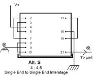
attached is another schematic of the circuit.
Thanks
Scott
attached is another schematic of the circuit.
Attachments
....So since there is no plate resistor, only the tubes internal resistance would be factored into the equation along with the turns ratio?
"only the tubes internal resistance" plus a 2.2K cathode resistor.
(The power supply, tube and resistor are in series across the primary.)
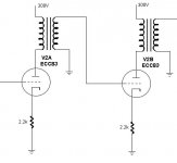
I was looking a the datasheet for the interstage transformer and noticed that the primary winds have a resistance of 625 ohms. Would that factor into the impedance equation?
Would this be correct?
internal plate resistance 62.5k
cathode resistance 2.2k
interstage primary winding resistance 625 ohms
First
ra'(unbypassed Rk) = ra + (mu + 1)*Rk
ra'=62.5k + (101)*2.2k
=284.7k
Second
R = ra' || Rp
R = 284.7k || 625 ohms
R = 624 ohms
Then if the interstage turn ratio is 1:1, the impedance at the secondary windings would be 624 ohm.
Or if the 625 ohms were not a factor, would
R = 284.7k
since there would be nothing parallel to ra'
jlsem - How do you determine the primary inductance for decent bass response? This is more of the information I have been looking for.
Thanks
Scott
Impedance of an inductor is 2 x Pi x f x L where f is frequency and L is inductance. There are several rules of thumb as to what impedance and frequency are selected but in simplest terms if you were to select an arbitrary frequency of 20Hz and choose the impedance to match the typical plate resistance of a 12AX7, say 75Kohms, then L would be 597H.
John
John
Thanks for the equation. So with a 597H inductance and 75k plate resistance, the frequency is flat down to 20Hz, then it rolls off. Is that correct?
Is there a way to figure out the cut off frequency if you know the inductance and resistance?
You suggest EC86 and EC88. Is that because of the lower plate resistance, higher current, or both.
Thanks
Scott
Is there a way to figure out the cut off frequency if you know the inductance and resistance?
You suggest EC86 and EC88. Is that because of the lower plate resistance, higher current, or both.
Thanks
Scott
I think that if you set impedance to equal plate resistance bass response is 3dB down at the chosen frequency. Someone may correct me if I'm wrong.
Both. Not to mention lower noise.
John
You suggest EC86 and EC88. Is that because of the lower plate resistance, higher current, or both.
Both. Not to mention lower noise.
John
I would like to continue asking questions on interstage transformers, so this thread seems appropriate. Hope you do not mind.
I see a lot of schematics with interstage transformers but the secondary is not loaded at all. For example this one on Andrea's great site:
300B PSE - Parallel Single Ended
After 5842 interstage there is no resistor parallel to the secondary. So for me there is no impedance on the primary or it is infinite? So where do I go wrong in my head?
Thank you in advance,
Pred
I see a lot of schematics with interstage transformers but the secondary is not loaded at all. For example this one on Andrea's great site:
300B PSE - Parallel Single Ended
After 5842 interstage there is no resistor parallel to the secondary. So for me there is no impedance on the primary or it is infinite? So where do I go wrong in my head?
You seldom want to load the secondary of an IST. You may have to if you're using an inferior IST, otherwise, avoid it as it'll increase distortion.
From xfmr theory, a winding with a load much greater than jwM (the case here) essentially "disappears". The IST basically operates no differently than a plate choke, as the unloaded secondary doesn't have any effect on the primary side. Or you could say that the unloaded secondary reflects an infinite load back to the primary, which appears in parallel with the r(p) of the driving tube connected to the primary, so the primary is still loaded by r(p) (as would be the case with a plate choke).
I think I am closer to understanding.
As I get it, interstage transformer is made best to be loaded by a high impedance, so that the output impedance is equal to the primary impedance or transformed primary impedance. I do not know where 10k comes from, maybe that just the measurements and specs were done with this load on the primary in mind... I imagine that the output transformers are done in the same way??
Regards,
Pred
- Status
- This old topic is closed. If you want to reopen this topic, contact a moderator using the "Report Post" button.
- Home
- Amplifiers
- Tubes / Valves
- Interstage transformer questions