The plate resistance of the drive tube plays an important role in the frequency response; both on the low AND HIGH end. That is because the 150H transformer windings have a resonant frequency on the order of 1kHz or so, lower for more inductance and higher for less. And for best fidelity consider that oldest of plate loads--the simple CHOKE. It has a +90 degree phase shift below resonance that smoothly changes to -90 degrees above resonance, so negative feedback may be applied across it no problem. Also the undistorted voltage swing is DOUBLED comparing to a resistor. So the best drive setup is a high S tube such as a 7788 or the frame grid section of a 6KV8; run in triode mode. Run off of a negative supply this will drive your low mu triode outputs direct coupled.

Attachments
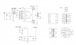
For low frequency the inductance of the transformer is important, but for high frequency also capacitances in the transformer are very important. The ideal choke or interstage transformer is not just a coil with a certain amount of windings but should be wound with the duty in mind. A good quality interstage transformer should be wound in isolated layers.
To simplify this whole thing....
Think of the mid band gain is mu of tube....provided the secondary is not loaded...can only do this with triodes..
Low frequency repsonse is based on the inductance ...
WHen the Inductive reactance is equal to the plate resistance you have your -3dB POLE.....
Chris
Think of the mid band gain is mu of tube....provided the secondary is not loaded...can only do this with triodes..
Low frequency repsonse is based on the inductance ...
WHen the Inductive reactance is equal to the plate resistance you have your -3dB POLE.....
Chris
In a typical application of an interstage, or driver transformer for a P-P amplifier the primary is a single winding plate load to the drive tube and the secondary is bifilar, with the center tap going to the output tube negative bias supply. The secondary ends couple directly to the output tube grids. Other than the grid-stoppers, NO resistors are required. The driver tranny is actually usually a trifilar winding; having a 1:1:1 ratio. Jack at Electra-Print offers a bifilar winding that may be used as a phase splitter; the simpler winding offers better phase and frequency characteristics; the application is similar to the choke driven SE amp.
- Status
- This old topic is closed. If you want to reopen this topic, contact a moderator using the "Report Post" button.