Michael Koster said:I'd call that a voltage regulator ;-)
No, it's a PS anti-filter. Or ripple generator.
")
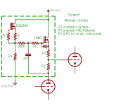
revintage said:This is how I would implement a Gyrator. Output voltage is set by adjusting R3. Note, devices and component values are random choice.
Hi Lars
The first time I saw something like that was from Broskie...and I liked the idea (simple, good for me
)... later on I found Jackinnj's work with the LR8N3 A very interesting feature of the LR8N3 is that it is said to be happy with a meager 0,5mA being drawn through it. I got some LR8N3 and some 400k/2W potentiometers with the intention of building regulated supplies for experiments. I would use a upper resistor of about 1k2 (to set current to 1mA) and the 400k to set the voltage, with maybe a smaller potentiometer in series to allow 'fine adjustments'...but I haven't got that far, yet...
Erik
No, it's a PS anti-filter. Or ripple generator.
Wavebourn, think again, youre so wrong.
revintage said:
Wavebourn, think again, youre so wrong.
Try the right leg of C1 to the ground and compare. You may add a Zener instead of how C1 is drawn now, to protect the gate against breakdown. Also, it will limit output current on a safe level defined by the resistor R1 value and Zener's breakdown voltage minus Vgs on that current (Ohm's law).
Edit: with 10 Ohm resistor and 12V Zener it will be something about 900 MA.
Michael Koster said:I'm trying to understand the purpose of R1 and C1 providing a high AC impedance when that circuit node has a 100uF cap to AC ground.What happens if R1 and C1 (and C3 for that matter) are removed?
I think if this were on a PCB and had 2 or 3 different connections toR1, it could be built as a screen regulator, a high impedance fixed voltage anode load, mu-follower, anti-triode, etc. It's a nice set of functions to have in one place..
On a related note, I'm looking at a DC filament gyrator as an alternative to filament chokes or VCCS. The circuit looks similar to yours but without C3. It would provide fixed voltage (on a controlled ramp) and present a (relatively) high AC impedance to the signal current on the filament.
Cheers, Michael
Originally posted by Wavebourn
Try the right leg of C1 to the ground and compare. You may add a Zener instead of how C1 is drawn now, to protect the gate against breakdown. Also, it will limit output current on a safe level defined by the resistor R1 value and Zener's breakdown voltage minus Vgs on that current (Ohm's law).
Edit: with 10 Ohm resistor and 12V Zener it will be something about 900 MA.
Michael, Wavebourn, could I ask you to post sketches of what you're talking about? A beginner at solid state circuitry, I'm trying to learn from you and am not sure if what I imagine from reading your words is even remotely similar to what you're talking about.
Also Michael, talking about Gyrators on filaments, did you see Rod Coleman's post? If you haven't already you might find it interesting. I built it in simple form (ie. much simpler rectifier and filter front end) and it works well/sounds good. Also tried a version with the top half of his circuit mirrored in the bottom, the whole thing fed by a current source.
Thanks
Hearinspace;
I was talking about Revintage's power supply. As drawn, it is powered from a voltage source with I assume some ripples that he tries to remove like a choke does. Unfortunately, a gyrator is not a choke, and it does not accumulate an energy, so I suggested him to turn it into a source follower that would be more effective in this particular application.
I was talking about Revintage's power supply. As drawn, it is powered from a voltage source with I assume some ripples that he tries to remove like a choke does. Unfortunately, a gyrator is not a choke, and it does not accumulate an energy, so I suggested him to turn it into a source follower that would be more effective in this particular application.
Wavebourn said:I was talking about . . .
Thanks, I'll look at that. BTW. I'm just about to sit down to try a couple of MJE5731A's in your High AC Impedance Load ('gyrator') circuit (The one you posted on the Anti-triode thread). Will post if I get it to do any tricks.
Thanks again for your help
Hearinspace said:
Thanks, I'll look at that. BTW. I'm just about to sit down to try a couple of MJE5731A's in your High AC Impedance Load ('gyrator') circuit (The one you posted on the Anti-triode thread). Will post if I get it to do any tricks.
Thanks again for your help
First of all, let's start from it's task. Whit kind of tube are you going to load? What voltage do you want on a plate? What B+ is in your possession? How big current do you need?
I was just going to try something/anything with a bench power supply. Dig up a tube that fits an already wired socket lying around the bench and start with that. However, If you are willing to lead me through the design process with something (which would be really awesome) then I'll choose something specific. How about a 417A. - Vpk = 150VDC /Ip = 18mA (Vg=-1.5VDC) I'll have up to ~500+VDC available for B+ (the output tube is a 10Y)
Thanks
Thanks
Hearinspace said:I was just going to try something/anything with a bench power supply. Dig up a tube that fits an already wired socket lying around the bench and start with that. However, If you are willing to lead me through the design process with something (which would be really awesome) then I'll choose something specific. How about a 417A. - Vpk = 150VDC /Ip = 18mA (Vg=-1.5VDC) I'll have up to ~500+VDC available for B+ (the output tube is a 10Y)
Thanks
Hmmm... For 350V/18MA it will be 20W dissipation on gyrator transistors.
Do you have also a 350V source? In such case gyrator will have to dissipate less than 4W.
Sure! The ~500V is being used to feed a cascoded Mosfet current source on the 10Y anyway. (It could use a little higher actually but the amp is being used to drive a very efficient horn so the overhead is not critical on the breadboarded version.) Using dropping resistance from that power supply output, I'm getting a tap at 290V for another CCS on the plate of the 417A for a total of 140VDC across the CCS. (of course the LED or Zener bias string will still be across ~290VDC but I've got a big enough resistor here somewhere) I can simply pull the existing CCS and swap in your circuit for a comparison.
Of course, If you specify 350V or any other V at the top of your circuit I can easily adjust the dropping R to get the desired voltage. I'm also happy to try other BJTs Mosfets etc if there are any specific ones you recommend for the circuit.
Of course, If you specify 350V or any other V at the top of your circuit I can easily adjust the dropping R to get the desired voltage. I'm also happy to try other BJTs Mosfets etc if there are any specific ones you recommend for the circuit.
I don't know how close are MJE5731A to specs so I would not risk, it may start breaking up exactly at 375 Volts.
Can you find a 350V Zener string and a N-type MOSFET that is specified for more than 500 Volts? Such a way you would regulate a voltage on about 350 V that will be safe for your PNP transistor that loads the tube in any expected and unexpected conditions.
Can you find a 350V Zener string and a N-type MOSFET that is specified for more than 500 Volts? Such a way you would regulate a voltage on about 350 V that will be safe for your PNP transistor that loads the tube in any expected and unexpected conditions.
Wavebourn said:I don't know how close are MJE5731A to specs so I would not risk, it may start breaking up exactly at 375 Volts.
Can you find a 350V Zener string and a N-type MOSFET that is specified for more than 500 Volts? Such a way you would regulate a voltage on about 350 V that will be safe for your PNP transistor that loads the tube in any expected and unexpected conditions.
I can put together something for the zener string without any trouble. How much drop on the zener itself do we want?
Will N-type depletion mode Mosfets work here ? - all I have are DN2540N5 (400V) and IXYS IXTP01N100D (1000V) . If they won't do I can get some of the irf9610 mentioned on the thread or whatever you recommend.
Just one other question. DO I really need 350V? Max positive swing on the plate of the 417A will be 150 + 60 so +/- 210VDC. I'm not complaining, just wondering why we need to worry about 350VDC. Are you thinking about start-up transients?
This is Great! Thanks Wavebourn!
Hearinspace said:
Michael, Wavebourn, could I ask you to post sketches of what you're talking about? A beginner at solid state circuitry, I'm trying to learn from you and am not sure if what I imagine from reading your words is even remotely similar to what you're talking about.
Also Michael, talking about Gyrators on filaments, did you see Rod Coleman's post? If you haven't already you might find it interesting. I built it in simple form (ie. much simpler rectifier and filter front end) and it works well/sounds good. Also tried a version with the top half of his circuit mirrored in the bottom, the whole thing fed by a current source.
Thanks
Here's what I would find useful as a modular bit of circuit, enclosed
in the dashed box. The current through R3 sets the DC voltage
to the gate of the anode load, and thereby sets the grid bias
voltage of the following tube. The mode of the output can be
changed by stuffing R1, R2, or both.
Cheers,
Michael
PS The filament gyrator is exactly what I had in mind. I like it better
than the VCCS approach.
Attachments
Why use a gyrator in a PSU? Really bad idea!
Better to use a capacitance-multiplier. This way you get low output impedance and don´t need expensive, high-quality caps at the output. Only a small plastic. The same amount of parts are needed. Ripple will even be lower or on par.
Simmed some variations(gyrator, ripple-generator, cap-multiplier) last night, will show them when I get home from work. The gyrator simme worst but all where good.
Michael, noticed you liked "my" HiZ DN2540 voltage-source .
Better to use a capacitance-multiplier. This way you get low output impedance and don´t need expensive, high-quality caps at the output. Only a small plastic. The same amount of parts are needed. Ripple will even be lower or on par.
Simmed some variations(gyrator, ripple-generator, cap-multiplier) last night, will show them when I get home from work. The gyrator simme worst but all where good.
Michael, noticed you liked "my" HiZ DN2540 voltage-source
.revintage said:Michael, noticed you had to many components in your circut above. Remove the 330k and make R3 330k instead. It will not be much current through the DN2540 so one might choose a smaller one(LND150?).
That would work fine but I also wanted the option to use a zener etc.
in place of R3 for more stable voltage setting if needed. It could be
used at a lower voltage that would make the resistor value too small,
so I added the extra resistor.
This is a candidate for a PCB so I wanted to have some options in
stuffing.
Michael
revintage said:Better to use a capacitance-multiplier.
I've got a couple TIP50's for this exact reason, but haven't played with them yet. Heat sinking can be a problem though. How much of a multiplication do you get? I've tried a Great Big 600uF 500v film capacitor which works pretty well too. It creates a space problem though due to size.
Michael Koster said:
That would work fine but I also wanted the option to use a zener etc.
in place of R3 for more stable voltage setting if needed. It could be
used at a lower voltage that would make the resistor value too small,
so I added the extra resistor.
This is a candidate for a PCB so I wanted to have some options in
stuffing.
My opinion is, it is ready for production. Some extra holes and traces may be added for different variants of current sources, but not necessary, if you are going to supply parts with PCBs.
- Status
- This old topic is closed. If you want to reopen this topic, contact a moderator using the "Report Post" button.
- Home
- Amplifiers
- Tubes / Valves
- Gyrator Question