There has been a lot of interest in a 12B4 line stage amp, and I thought the time had come to take a second look, post some findings, get the help of the group, and put together a really good version we could all use.
I really like the 12B4A--it has a lot going for it.
- Very low plate resistance means
. Low output impedance w/o extra CF stage (which I hate)
. High current capability--could double as headphone amp
. Choke fed drive available for high voltage SET
- Cheap and available: rolling to select won't break the bank
- Lo mu
. You don't need more than 12db gain in a line stage
. Low distortion
. Good for Grounded cathode design
It aslo has a few problems to work through
- Not as linear as say a 5687 or 6DJ8
. Means careful attention to working region
. Can't over-drive without consequences
. Runs best in high current regions
I'll start posting results and design thoughts--the final version will show up on my website: www.galaxySETlabs.com
Cheers
coffeedj, re the following issues:
At around 100V – 200V and 20mA they are as linear as any 5687.
I reckon they sound best around 20mA, sounding rather ‘thick’ and slow at 30mA.
It aslo has a few problems to work through
Not as linear as say a 5687 or 6DJ8
Runs best in high current regions
At around 100V – 200V and 20mA they are as linear as any 5687.
I reckon they sound best around 20mA, sounding rather ‘thick’ and slow at 30mA.
1st results
The first test I did was to look at performance in a basic minimum grounded cathode design. Parameters are:
Load = 10K
Input R = 220
Cathode bypass = 100uF
WHat I've discovered using various values of B+ is that the 12B4 operates best at high voltage and high current. That means that the grid bias ranges from -12 to -22V, which seems excessive for a line stage, but it works well and is not a problem.
In the basic GC design you get about 9b of 2nd harmonic distortion reduction moving from 100V B+ to 200V, and another 2 db moving to 255V, and viturally no change if B+ is increased beyond that. The third harmonic is independent of B+ voltage and relates only directly to input voltage. These results are fairly independent of the cathode resistance as long as you keep the cathode current above 10ma.
The other thing that is noted for the basic GC design (using optimum parameters from above) is that as long as the output signal is limited to approximately 0 db (1 V RMS or 2.4V P-P), the distortion is not measureable for any harmonic (which is >65db down on my Techtronics TPS 2024). With the 12B4 giving gain of about 5--assuming a anode load of 5K or greater--that means an input signal of .250V RMS, or -6db will drive to full output.
Since most power amp designs require somewhere between .25 and 1.0V RMS to drive to full power, and most CD's are mastered to 0 db for full power, and most phono amps will drive to 0 db or greater, that means that a basic GC design will work quite well for a pre-amp. This is simplicity in the max--one tube, two resistors, two capacitors and an input VC.
However, most commercial pre-amps are made to drive more output. THe Cary SLP-05, for example, will output about 20V P-P of clean signal. Is this necessary? The simple answer is no. In fact means that you are always running the Volume Control at minimum on the Cary. The longer answer is that you would like to be able to drive up to about 2V RMS with no distortion out of the line stage in order to meet overload requirements from the phono stage. The CD will never overload past 0 db (1.0V RMS) because that is how the CD output is defined. So if you only use CD's you could quit here. You can build a very cheap and simple line stage.
For Vinyl enthusiasts, we need to work a little harder, unless your power stage requires .5 RMS or less. Then you are there already, but it is no fun to quit the design at this point so let's keep going.
Next thing to look at is voltage regulation and current sources. The guru's on this forum will hopefully weigh in. I'm going to look at a simplest solution first.
One final note on dynamic range. It is interesting that although CD's have theoretically more dynamic range than Vinyl, the actually listening requirements seem reversed. This is because most CDs are mastered with the music compressed. This especially true for POP where a total dynamic range of 15 db is not unusual for a recording! Jazz is better, and classical usually has the highest dynamic range, but people don't listen to classical at ear splitting levels so it kind of all balances out from the design perspective.
A notice. 12B4 needs 3.3k CC resistors on both pins 2&7 so to work oscillation free. At least it happened to all of those I have seen.
Also people must know that 12B4 is microphonic upon slight impact on glass or chassis when giving gain. It will ''ping'' but it is nothing like a DHT. I don't care about that, but it is enough reason for some to pass it.
Also people must know that 12B4 is microphonic upon slight impact on glass or chassis when giving gain. It will ''ping'' but it is nothing like a DHT. I don't care about that, but it is enough reason for some to pass it.
salas said:What make gave you the least? RCA's and Sylvanias are sounding good, but I haven't come across one that could pass the fingernail knock test unless configured as a follower.
Salas,
Have you tried silicone rubber "O" rings mounted over the micas?
---------------------------------------------------------------------------------------
All,
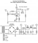
I'm attaching my version of a 12B4 line stage. I used CCS loading, which allows the NASTY 10 KOhm IHF "standard" load to be driven.
Attachments
Eli Duttman said:
Salas,
Have you tried silicone rubber "O" rings mounted over the micas?
No, I like the sound as it is since it does not have a microphonic echo. Just to inform those who haven't experienced a 12B4 and may think its ''dead'' due to low mu. The big hot cathodes are sensitive.
I have used a cascode Mosfet CCS (enhancement mode) with plate at 160V to ground, 1k2 cathode resistor BGNX bypassed, with 18V across (15mA). Up to 20mA is OK. Also tried Jung's 317 10M45S cascoded. But best sound is with constant voltage enhancement cascoded Mosfet Gyrator based on a Wavebourn's idea. But with a 12B4 care is needed to PSU decoupling unless the whole active thing reacts and blows serious hiss. With resistor load is easier to keep tame. Active loading pushes the Mu and if there are hidden gremlins they come out. FFT scrutiny is advised during building.
You have several CCS options:
Gary Pimm ccs http://www.pacifier.com/~gpimm/self_bias.htm in the anode (in my view the best sounding option)
Simple DN2540 or IXCP10M45 s cascode ccs in the anode (my second preference)
DN2540/IXCP10M45s - LM317 hybrid in the anode as per Walt Yung (untried)
http://www.audioxpress.com/magsdirx...ia/jung2778.pdf
http://www.audioxpress.com/magsdirx...ia/jung2779.pdf
Bypassed LM317 ccs in the cathode (as proposed by Brian Beck in the huge 12B4 thread)
Bipolar ccs in the anode(eg Bottlehead & DIYaudio group project)
Of course YMMV.
I haven't tried the Wavebourne gyrator option described by Salas. it would be great if someone could post a schematic.
great, i will be following this thread....
i've just taken arrival of a psu that has been almost completley built for me by a friend.... it has a couple of large chokes and capacitors and a smaller circuit to change the heater supply to dc. I measured 330v at the B+ but was told that this should reduce to 280V with a load attached. The reason i went for this psu is because i was inspired by some older posts about the 12b4 and decided it would be my first diy project..... i'm interested in machs comments about the tubes prefered operating voltage of 100v - 200v, i was just going to build franks simple design? are there any improvements to this design and how important is the operating voltage? any tips for newbie will be much appreciated,
cheers stuart
oh btw coffee, i love my vinyl too, the 12b4 linestage will be driving a leak stereo 20, fed by a modest project phono pre and thorens deck. Celestion 66 monitor coffins... and i can't deny a little digital influence, i have a half decent dac and use a pc as transport....
is the 12b4 still for me in your opinion? or would i be better looking at 5687?
stuart
is the 12b4 still for me in your opinion? or would i be better looking at 5687?
stuart
mach1 said:You have several CCS options:
Gary Pimm ccs http://www.pacifier.com/~gpimm/self_bias.htm in the anode (in my view the best sounding option)
Simple DN2540 or IXCP10M45 s cascode ccs in the anode (my second preference)
DN2540/IXCP10M45s - LM317 hybrid in the anode as per Walt Yung (untried)
http://www.audioxpress.com/magsdirx...ia/jung2778.pdf
http://www.audioxpress.com/magsdirx...ia/jung2779.pdf
Bypassed LM317 ccs in the cathode (as proposed by Brian Beck in the huge 12B4 thread)
Bipolar ccs in the anode(eg Bottlehead & DIYaudio group project)
Of course YMMV.
I haven't tried the Wavebourne gyrator option described by Salas. it would be great if someone could post a schematic.
Because I have tested all you mention except the G.Pimm. I recommend you to try the constant voltage gyrator. It sounds different (to me clearly better). Wavebourn uses the principle, we talked about it during an anti-triode CCS discussion. I have put together this one and Wavebourn inspected it in that thread. Gave the green light. If you use a regulated B+ common between channels, see it does have a low output impedance between 20kHz to 50kHz. The gyrator is constant current on AC, constant voltage on DC. Its an electronic choke as you know. It will just keep your B+ at half or about. It is not like changing points by varying a CCS. B+ choice is the key so to hit the bias you look for. I think you use depletion a lot, may you can come up with something without LEDS (needed to turn on enhancement mode) possibly? I haven't looked in to it yet. Talking about the LEDS, they don't connect to the top Mosfet's gate at all on the circuit shown, they turn on the lower one only, six of them. I mention the obvious bcs on the schematic it may be read as a possible junction that I forgot the dot.
") The upper divider resistor turns on the upper PMosfet. Its a servo loop with the anode. It gives double the dynamic headroom than a CCS when nominal current is reached. Like an SEP anti-triode at that.
The upper divider resistor turns on the upper PMosfet. Its a servo loop with the anode. It gives double the dynamic headroom than a CCS when nominal current is reached. Like an SEP anti-triode at that.Attachments
surfstu said:great, i will be following this thread....
i've just taken arrival of a psu that has been almost completley built for me by a friend.... it has a couple of large chokes and capacitors and a smaller circuit to change the heater supply to dc. I measured 330v at the B+ but was told that this should reduce to 280V with a load attached. The reason i went for this psu is because i was inspired by some older posts about the 12b4 and decided it would be my first diy project..... i'm interested in machs comments about the tubes prefered operating voltage of 100v - 200v, i was just going to build franks simple design? are there any improvements to this design and how important is the operating voltage? any tips for newbie will be much appreciated,
cheers stuart
Before you change your B+, try 160V on anode to ground at 15mA. Its a very nice point.
mach1 said:thanks Salas !
You are welcome. I will be interested to know the course of your experiments and your sonic impressions if you try something based on that, bcs as far as I know, nobody else did that with Mosfets on low mu tubes in line stage. Wavebourn does it on Novals BJT cascoded, in mic stages.
CCS on 12B4 and microphonics
The rubber rings definately help. And I've found RCA to pretty good w/respect to lower microphonics.
I like your stage--simplicity in the max. I especially like the low voltage--in fact I was hoping to find that a simple isolation transformer could supply B+.
I threw a CCS together and measured the differences to Basic GC. 2nd harmonic distortion rejection is about 4 db better than GC at 255V--very nice. 3rd harmonic remains about the same. Square response is good--not quite as clean though. Gain is better by a little (obviously) do to ultra high AC resistance delivered to the plate. I ran mine at 21 ma, 120V B+, 110V to Plate. All in all, a very nice solution. Falls apart at about the same input voltage as GC, but with higher gain comes closer to goal of 2V output.
One potential comparison would be a choke fed anode resistance at the same voltage and cathode resistor of 500ohms and in the CCS design above. Gain is close to same as CCS and 3nd Harmonic distortion in better by about 4 db! 2nd harmonic is comparable and down over 60db. I'm a big fan of choke anode loads, so I'm going to proceed with this.
Next thing to look at is tube based voltage regulator. With only 120V required at 20ma, 0B2 for each channel could be an option.
12B4 vs 5687
I think they will be equivalent for this project. The 5687 is a better choice for high voltage drives--think 2A3, 300B---but in lower outputs I haven't detected any difference.
For guitar amps I love the 12B4 because I can run it right around break up point and get fabulous distortion blues.
With respect to Power Supply--I think a isolation tranny will do the trick for this project. No need to waste a good HV transformer.
I like your stage--simplicity in the max. I especially like the low voltage--in fact I was hoping to find that a simple isolation transformer could supply B+.
An acquaintance made that drawing from a narrative I provided. The values shown reflect stuff in his "junk box".
For a builder starting from scratch, I recommend a Triad N-68X for B+ and a Triad VPL24-1100 for heater power. That inexpensive (total $21.73 from Allied) "iron" will get the job done in both "120" and "240" VAC household power zones.
The pseudo choke I/P filter shown is reasonably well regulated, on its own. Adjust the "fudge factor" cap. to bring the rail voltage in (under load) between 120 and 125 VDC. The most expensive part in the design is the 1st PSU inductor, which must be "beefy".
BTW, cheapskate Eli thinks in terms of a film and foil bypassed GE 40L3501 MPP part for the O/P coupling job. Mundorf caps. are very nice and very expensive. The Law of Diminishing Returns applies here.
- Status
- This old topic is closed. If you want to reopen this topic, contact a moderator using the "Report Post" button.
- Home
- Amplifiers
- Tubes / Valves
- 12B4 Line Stage Amp