Final testing on 12B4 Choke fed design
Final test for this pass (maybe first--maybe last) was to try voltage regulation with the choke fed design.
First attempt was an 0C3--but the voltage was too low at plate. Changed to the 0D3 and the plate voltage using my 150H choke, gives 110V at the plate: Just perfect.
Checked out the performance--and I'm convinced. The input voltage before break up is almost 80% above the CCS design--660mv RMS, giving a clean 3.6V RMS or 10V P-P output. This is excessive overdrive capacity. Distortion at the same operating points is unmeasureable on my FFT, and the 3rd harmonic has mainly dissappeared. 10KHz square wave looks wonderful.
There is something to be said for simple, old technology. I'm going to build this and see how it sounds.
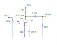
Final details are as follows:
Textbook Grounded Cathode design
Paralleled 2.2K resistors input to grid
Cathode resistor = 510 ohms, 1 Watt minimum
Cathode Current = 21ma, Vg=-11.2
Anode Choke = 150 H, 1.9K DCR
Regulator tube = 0D3, 155V regulated
Voltage at Plate = 110V
Gain = 5.5, Max output = 10V P-P
I'll get it drawn up and post it in the next few days. First need to design the power supply. With the OD3 requirement my hope of just using an isolation transformer has died. Oh Well.
For those who need parts (12B4's & chokes) I'll make them available on my web site. I have my chokes built for my by a master designer in Hong Kong who ships them in bulk to me. His quality is excellent--easily rivaling Electroprint or Tamura.
This has been fun--I'll be signing off for a few days. Got a biz trip coming up.
-coffeedj
Final test for this pass (maybe first--maybe last) was to try voltage regulation with the choke fed design.
First attempt was an 0C3--but the voltage was too low at plate. Changed to the 0D3 and the plate voltage using my 150H choke, gives 110V at the plate: Just perfect.
Checked out the performance--and I'm convinced. The input voltage before break up is almost 80% above the CCS design--660mv RMS, giving a clean 3.6V RMS or 10V P-P output. This is excessive overdrive capacity. Distortion at the same operating points is unmeasureable on my FFT, and the 3rd harmonic has mainly dissappeared. 10KHz square wave looks wonderful.
There is something to be said for simple, old technology. I'm going to build this and see how it sounds.
Final details are as follows:
Textbook Grounded Cathode design
Paralleled 2.2K resistors input to grid
Cathode resistor = 510 ohms, 1 Watt minimum
Cathode Current = 21ma, Vg=-11.2
Anode Choke = 150 H, 1.9K DCR
Regulator tube = 0D3, 155V regulated
Voltage at Plate = 110V
Gain = 5.5, Max output = 10V P-P
I'll get it drawn up and post it in the next few days. First need to design the power supply. With the OD3 requirement my hope of just using an isolation transformer has died. Oh Well.
For those who need parts (12B4's & chokes) I'll make them available on my web site. I have my chokes built for my by a master designer in Hong Kong who ships them in bulk to me. His quality is excellent--easily rivaling Electroprint or Tamura.
This has been fun--I'll be signing off for a few days. Got a biz trip coming up.
-coffeedj
thanks everyone, my head is still spinning from the techical but i've gathered some useful info. I'm now debating between 12b4 and 5687... which brings me to another problem... I recently built some silver interconnects which i'm very happy with. I noticed an immediate difference across the range but the highs and mids seem more prominent in my system. The bass clarity has improved also but it seems to have sunk to the back a little. So now i'm wandering if this preamp is going to further extend the mids in the classic tube style? Is it easy to provide some kind of bass control to this preamp? and what would push the bass more, the 12b4 or the 5687?
stuart
stuart
I noticed an immediate difference across the range but the highs and mids seem more prominent in my system.
This is a classic outcome of switching from copper to silver. If your system has been voiced using copper, then switching to silver will often change the sound in exactly the manner you describe. It's funny that your description concurs with my findings and those of just about everybody I know who has tried silver; yet there are still many contributors on this forum who will tell you that the difference between conductor material is not audible and that what you have observed is all in your mind.
If I would like to use a grid bias battery in the schematic posted by mach1 a few posts above this one, does the battery have to be re-chargeable ? Some batteries (Lithium?) explode when any form of charge is applied to them if they are not re-chargeable. (A cathode bias battery would of course need to be re-chargeable.)
bequerel said:If I would like to use a grid bias battery in the schematic posted by mach1 a few posts above this one, does the battery have to be re-chargeable ? Some batteries (Lithium?) explode when any form of charge is applied to them if they are not re-chargeable. (A cathode bias battery would of course need to be re-chargeable.)
Hi,
I know for sure that the cathode bias battery do not require recharging because the are being charge while in use... use a rechargable battery here and you are saft from any explosion.
Keen to know the other parts of this question as well.
Cheers
Ken
Audio_idiot said:
Hi,
I know for sure that the cathode bias battery do not require recharging because the are being charge while in use... use a rechargable battery here and you are saft from any explosion.
Keen to know the other parts of this question as well.
Cheers
Ken
Yes, the cathode battery operation is OK, the question is the grid battery.
I am not worried about having to re-charge, but if the battery will explode if I use an ordinary battery on the grid.
thanks mach1,
so what will the 12b4 do with regards to the tone? and is it easy to add some bass in the final output of the linestage? should i just return to good old copper? I didn't understand what you meant by 'voicing' my system with copper... does this mean it has been 'run in' by copper wirring?
cheers stuart
Its heavier sounding with resistive anode load, cleaner and faster with active anode load. Also use a large (470-1000uF) bypass cap for the cathode R, sounds bulkier that way. A Silmic II is rounder than a BG or Nichicon there for example. See for A.B. or similar carbon resistors too. All those choices tune the tone towards to the rounder side of reality. That may offset enough the silver sheen you observed and disliked on top of the clarity gains you got with your new cabling.
mach1 said:
This is a classic outcome of switching from copper to silver. If your system has been voiced using copper, then switching to silver will often change the sound in exactly the manner you describe. It's funny that your description concurs with my findings and those of just about everybody I know who has tried silver; yet there are still many contributors on this forum who will tell you that the difference between conductor material is not audible and that what you have observed is all in your mind.
My thought, untested, is that it is a result of the lower capacitance of silver wire which would affect the highs. As for Bass respsonse--that could be affected to lower resistance.
I also think that the major difference may not actually be in the conductor itself, but rather in the solder joints. Just the method of wrapping and attaching wires can subtely change things.
Thankyou to the experts! and yes, I was dubious as to whether the difference in cabling would be noticeable, and although I admit to imagining all sorts of strange things in the past, the difference I experienced was undeniable - almost like listening to a different amp.
To get this thread back on it's rightful path, I'm still sat here with an amazing choke input power supply (too embarrassed to tell you how much it has cost me) and am looking to build a simple linestage as my first project. I feel a little guilty as it was me who swerved this thread toward a copper/silver discussion.
I believe I will retrieve an amount of bass back from the 12b4 linestage, other members have commented on how a passive pre can rob one of bass. And i think this and the change to silver had me feeling robbed.....
Am i picking a tricky tube as my first linestage? Maybe I should build it and then worry about the bass....
cheers stuart
Active Loads and 5687's vs 12B4
I actually have a different opinion about active loads, which is why I don't like them. By definition, an active load uses feedback, which will modify the harmonics differently than the fundamental--unless the amplifier is utterly linear. As a violiinist I can hear this, probably because a violinist trains their ears to hear harmonic changes in order to tune double and triple stops correctly. I do not like cathode followers for that reason (100% negative feedback) because I can hear the subtle phase shifts introduced.
A lot of times what some people call cleaner and faster is to my ears just high frequency phase distortion in the harmonics.
A related example is what a cymbol sounds in concert vs on a CD recording. You can tune your system to make a cymbal sound bright and forward and think it is great--until you go to a classical concert and hear a cymbol and realize they don't sound anything like what your system reproduces. Live music is much more l laid back and even more 'heavy' than is commonly reproduced. The bass content is also much less than often mastered on the recording. THat doesn't mean you have to like the sound of live music--I do and so try to design to mimic that as close as possible. Having an artificial sound is valid--it just depends on what you like. THat's what makes audio great, no opinion is wrong.
This affects the decision on 12B4 vs 5687. If you like active loads the 5687 or the 12B4 works. The difference of rolling tubes is probably equivalent to the difference of the two designs. If you want to use a choke load like I do--then the 12B4 is a better choice due to the lower plate resistance and thus lower choke requirements to get full bass response. Alternatively you can parallel the two sections of the 5687 and get a lower plate resistance.
One final note on silver--in speaker coils in produces a smoother response. Copper is 'brighter' by comparison.
salas said:Its heavier sounding with resistive anode load, cleaner and faster with active anode load.
I actually have a different opinion about active loads, which is why I don't like them. By definition, an active load uses feedback, which will modify the harmonics differently than the fundamental--unless the amplifier is utterly linear. As a violiinist I can hear this, probably because a violinist trains their ears to hear harmonic changes in order to tune double and triple stops correctly. I do not like cathode followers for that reason (100% negative feedback) because I can hear the subtle phase shifts introduced.
A lot of times what some people call cleaner and faster is to my ears just high frequency phase distortion in the harmonics.
A related example is what a cymbol sounds in concert vs on a CD recording. You can tune your system to make a cymbal sound bright and forward and think it is great--until you go to a classical concert and hear a cymbol and realize they don't sound anything like what your system reproduces. Live music is much more l laid back and even more 'heavy' than is commonly reproduced. The bass content is also much less than often mastered on the recording. THat doesn't mean you have to like the sound of live music--I do and so try to design to mimic that as close as possible. Having an artificial sound is valid--it just depends on what you like. THat's what makes audio great, no opinion is wrong.
This affects the decision on 12B4 vs 5687. If you like active loads the 5687 or the 12B4 works. The difference of rolling tubes is probably equivalent to the difference of the two designs. If you want to use a choke load like I do--then the 12B4 is a better choice due to the lower plate resistance and thus lower choke requirements to get full bass response. Alternatively you can parallel the two sections of the 5687 and get a lower plate resistance.
One final note on silver--in speaker coils in produces a smoother response. Copper is 'brighter' by comparison.
surfstu said:
Am i picking a tricky tube as my first linestage? Maybe I should build it and then worry about the bass....
cheers stuart
The 12B4 is a great starter linestage. As to you power supply it can work fine with this design (posted as a work in progress--I haven't completed the testing and listening). This design requires 200V at 80 ma, and a good power supply is absolutely vital. You can use various techniques to drop the voltage as needed and retain the speed.
I'll post the full size and design on my website later this week.
Attachments
salas said:I did not say correct. I said cleaner, faster.Correct must be the overall system balance.
Absolutely -- I stand corrected.

Stuart,
In my experience the 12B4 is very neutral, with 5687s veering towards a darker, fuller sound (although as coffeedj mentioned there is quite a bit of variability between tube manufacturers). By ‘voicing’ I mean selecting components that give you a balanced sound (or a specific type of sound you trying to achieve). The components that give a balanced sound with copper wiring are likely to sound a bit biased towards the mids and top end if you change to silver. This is what salas was alluding to: warm sounding components like AB resistors and silmic / pio capacitors are more likely to result in a balanced sound with silver than say vishay bulk foil resistors and os-con caps.
When I tried silver, I perceived greater clarity in the mids and highs (a very seductive effect), but ultimately found the unbalanced sound very fatguing to listen to for any length of time.
Bequerel,
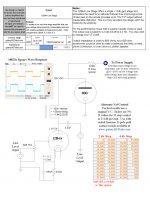
The linestage schematic I posted had a couple of minor errors (two dots indicating connections were missing) that have been corrected in this version.
Coffeedj,
Will you be offering suitable chokes for sale ?
In my experience the 12B4 is very neutral, with 5687s veering towards a darker, fuller sound (although as coffeedj mentioned there is quite a bit of variability between tube manufacturers). By ‘voicing’ I mean selecting components that give you a balanced sound (or a specific type of sound you trying to achieve). The components that give a balanced sound with copper wiring are likely to sound a bit biased towards the mids and top end if you change to silver. This is what salas was alluding to: warm sounding components like AB resistors and silmic / pio capacitors are more likely to result in a balanced sound with silver than say vishay bulk foil resistors and os-con caps.
When I tried silver, I perceived greater clarity in the mids and highs (a very seductive effect), but ultimately found the unbalanced sound very fatguing to listen to for any length of time.
Bequerel,
The linestage schematic I posted had a couple of minor errors (two dots indicating connections were missing) that have been corrected in this version.
Coffeedj,
Will you be offering suitable chokes for sale ?
Attachments
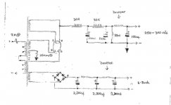
ah, a little knowledge can go a long way to bug a person! And i Just spent all that pocket money on silver wire/WBT connectors. Fatigue is a good description. Thanks for the info though, it makes sense, think I will build the 12b4 pre and see whether i want to return to copper. I spoke to my mentor today who helped with the power suply, I sent him the schematic attached and he's going to put together a parts list of the closest components he has got. I think the only change he will make is the addition of a 'Y' splitter, made of a few capacitors and bleeder resistor, to ensure the B+ arrives cleanly down the umbilical cord from the PSU. He said the components to play about with are the .33uf and 360uf capacitors and I think he is from the old school of using much smaller capacitors, although he will match the schematic and i can make any changes I want later.
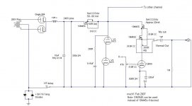
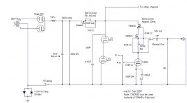
I've also posted a schematic of the psu, although i'm sure it is all kindergarden to you guys..
thanks again, stuart
p.s. i hope i'm not treading on toes posting the linestage diagram, i believe i found it on this site.
I've also posted a schematic of the psu, although i'm sure it is all kindergarden to you guys..
thanks again, stuart
p.s. i hope i'm not treading on toes posting the linestage diagram, i believe i found it on this site.
Attachments
mach1 said:Stuart,
Coffeedj,
Will you be offering suitable chokes for sale ?
Yes -- I have a good stock of them, and I'm sending a new order to HongKong in the next few weeks.
surfstu said:and the psu....
Yes--pretty standard. Couple of points I migh recommend:
1. I would double the LT final stage capacitance at minimum. You will still get a fair ripple out of this LT DC supply. I use surplus motor caps in the 100,000 to 250,000uF range for the last stage heater voltage filter. Get these for about $1 at local surplus shops. Also, make sure to ground the heater voltage--it can't float or you will induce hum. If you do want a 'pseudo' float then bridge a 50 ohm reistor off each leg to ground.
2. 360uF on Cathode bypass is overkill and will not improve sound--may actually degrade it. I would change to 100uf and bypass with oil/paper 1-10 uF.
3. Couple of easy ways to drop HT voltage w/o losing ps response: (a) use a variac (not always a solution, but I do it, (b) add another PI choke section and get rid of the dropping resisitor. The final choke will not need to be rated as high because all the filtering has taken place by this point--thus saving $. It will give better perfromance than the dropping resistor and you can choose the appropriate DC resistance to get the appropriate output voltage.
4. Final ps capacitor can be bigger if hum is a problum (180-360uF), but whatever the size it should be bypassed with a non-EL that is approx 1/100 the value of the EL cap. You are not using regulation or hum-bucking on your design, so ultra clean B+ is a must.
5. 12B4 doesn't necessarily need DC filament voltage--but if you have it that is great. 12.5 VAC CT using all three heater pins generally does the trick as well--make sure to twist leads tightly.
YMMV, but this is what I would do.
- Status
- This old topic is closed. If you want to reopen this topic, contact a moderator using the "Report Post" button.
- Home
- Amplifiers
- Tubes / Valves
- 12B4 Line Stage Amp