Hello,
I'm quite new to tube amplification, and to improve my knowledge, I've decided to try to fix a friend's vintage guitar tube amp'.")
The amp is a GEM Electronics (Italian brand) "Deluxe 10" model. It was probably build in the end of 60's.
I've found what was wrong, I've drawn the amp schematics and to complete my work, I'd like to determine what kind of resistors are to be used in place of the original ones, in case somebody would like to build his own "Deluxe 10"...
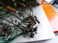
In the attached file, you can see a picture of the resistors.
Type A is only found on the grid of the EL84 and is the only one of this type. Is it a 1/2W or 1W resistor ? Metallic type or Carbon ? I've read that carbon type a more noisy, that could explain the metallic one on the grid of the power tube ?
Type B is found everywhere... Again, I don't know if those are 1W or 2W resistors ?
If someone could help me, I would be quite happy to finalize my brief study... Thanks !
BTW, if somebody is interested in getting the schematics or some photos, I could share them with pleasure.
Regards.
Nicolas.
I'm quite new to tube amplification, and to improve my knowledge, I've decided to try to fix a friend's vintage guitar tube amp'.
The amp is a GEM Electronics (Italian brand) "Deluxe 10" model. It was probably build in the end of 60's.
I've found what was wrong, I've drawn the amp schematics and to complete my work, I'd like to determine what kind of resistors are to be used in place of the original ones, in case somebody would like to build his own "Deluxe 10"...
In the attached file, you can see a picture of the resistors.
Type A is only found on the grid of the EL84 and is the only one of this type. Is it a 1/2W or 1W resistor ? Metallic type or Carbon ? I've read that carbon type a more noisy, that could explain the metallic one on the grid of the power tube ?
Type B is found everywhere... Again, I don't know if those are 1W or 2W resistors ?
If someone could help me, I would be quite happy to finalize my brief study... Thanks !
BTW, if somebody is interested in getting the schematics or some photos, I could share them with pleasure.
Regards.
Nicolas.
Attachments
Hi Nick,
The A resistor appears to be a film resistor. Whether it's a carbon or metal film is difficult to say. Probably a carbom film and it looks like a ½ watt rating. Prefectly acceptable type to use here. And since it's on the grid, a higher wattage is unnecessary. The other B resistor is a carbon composition type and looks to be ½ watt also. Wattage is based on physical size, and I'm looking at the other components near by.
Victor
So you think both are 1/2 W, despite their different size ?
I have to study the different types of resistors...
As it's not easy to guess dimensions on a photo, I've taken some measures :
Type A : diameter=2.2mm length=7.5mm
Type B : diameter=3.6mm length=9.4mm
Thanks for your help!
I have to study the different types of resistors...
As it's not easy to guess dimensions on a photo, I've taken some measures :
Type A : diameter=2.2mm length=7.5mm
Type B : diameter=3.6mm length=9.4mm
Thanks for your help!
nio101 said:So you think both are 1/2 W, despite their different size ?
Yes. First I enlarged and lightened the photo to see it better. Then comparing "B" to the others as well as the terminal tie point, the tube sockets and body to wire size, it's a ½ watt. Carbon comp resistors have a thick molded body over the carbon rod that provides the insulation. Were you to break one in half, you would see this. A film resistor has only a thin coating of something (epoxy?) over the film-coated ceramic rod for insulation. Trust me, I've been working with electronic components long enough to have developed a well calibrated eyeball.
Thanks, Victor !
Here is a link to some pictures of the old basic amp and the soon-to-be-released schematics :
http://tenuki.fr/blog/?page_id=47
It's in french at this time, but I could translate it if some people are interested... (it might only be interesting for newbies like me).
Here is a link to some pictures of the old basic amp and the soon-to-be-released schematics :
http://tenuki.fr/blog/?page_id=47
It's in french at this time, but I could translate it if some people are interested... (it might only be interesting for newbies like me).
I would be interested to see the schematics.
As far as the resistors go, they are not real costly so I always err on the side of caution and calculate their current and voltage and double (at least) the wattage.
I hate to make assumptions about what a manufacturer might have used. For instance if a resistor is dissapating .49 watts and they used a 1/2 watt resisitor any other small changes in the circuit "might" increase that over the 1/2 watt at some point. I would always replace that with a 1 watt of similar composition.
If you post schematics with English descriptions that is suitable enough for most of us that speak any other language.
Only here in the US do we ASSUME that we need not learn any other language.
Schematics tend to be readable in ANY language (other than Cyrillic )
Ok, here are the schematics for the power supply and the amp.
An empty socket can be seen on the amp, with some 1N4006 soldered around... So I guess it was for a rectifier tube ?
I still have to double-check the schematics with the hardware and write down the capacitors max voltage, but it gives a good idea of this simple design.
I don't know how much wattage the amp could give, but I guess it couldn't give more than 10W with a single EL84 ?
Whatever the power, the little amp sounds great and is fun to play the guitar on...
Well, while looking at the schematic, I was asking myself why the supply voltages are still different at OPT, Vsupp0 et Vsupp1 with no load (no tube in the sockets) ?
If no lamps are in place, the condensators should charge in the amplification circuit then no current should go through R2 nor R3, then the voltages at OPT, Vsupp0 and Vsupp1 should be the same ?
I really don't see why it is not the case if I do the test !?!
Attachments

Difficult to judge size of the topmost resistors (4K7 and 1K5); I would agree with Hollowstate's findings.
But I have a question about two component values on your schematic.
R19=150K is a cathode bias resistor. Can you check that this is not perhaps 150 ohm? (150K will not work.)
R11=470 ohms - the opposite! This would make sense at 470K, not 470 ohms.
And that anti-hum switch!! I guess that from switch-earth there was probably a 47nF capacitor, not a direct connection!
Then resistors from that age often drifted considerably off the nominal value. Do check that. If you are serious about this amplifier it might be worth-while to replace all resistors with 1/2W - 1W metal-film types. They are mostly 1-2% these days; materials have developed significantly since the 60s. It might also help to replace capacitors, especially electrolytics. 50 odd years are a long time for electrolytic capacitors from the then time!
Edit: Sorry, I have just noticed a 10K resistor in the 6V heater supply (R22). That can also not be true, not even 10 ohms. Are you sure about that?
OOPS!
Sorry!!!
I did not magnify it enough and the wire to Pin 1 looked shorted to the other side of the tranny.
coldcathode said:Did anyone notice the Secondary of the PT tranny is DEAD SHORTED?
Sorry!!!
I did not magnify it enough and the wire to Pin 1 looked shorted to the other side of the tranny.
Hello,
You were right, Johan, on every point !
Here is a revised version.
Thanks for your advice, I'm going to change all the resistors and capacitors for new ones...
I noticed the real heater voltage is not at 6.3V, but closer to 6.5V/6.6V. Is there a simple way to bring it back to 6.3V ? I read somewhere it was quite important for tubes...
I was thinking of putting a 0.1 Ohm in the heater circuit ?
Attachments
nio101 said:I noticed the real heater voltage is not at 6.3V, but closer to 6.5V/6.6V. Is there a simple way to bring it back to 6.3V ? I read somewhere it was quite important for tubes...
I was thinking of putting a 0.1 Ohm in the heater circuit ? [/B]
You could put two schottky diodes facing the opposite direction, connected in parallel into the heater supply. This would lower AC voltage by 0.3V.
As others have pointed out there are some odd value components in your schematics. Perhaps you should use an ohmmeter to determine real values and use these as a clue to what the color codes really stand for ?
- Status
- This old topic is closed. If you want to reopen this topic, contact a moderator using the "Report Post" button.
- Home
- Amplifiers
- Tubes / Valves
- Wattage of vintage resistors ?