Hello all,
Well, I've been puttering about with that "High Power Ultra-Linear Williamson" for a couple of weeks now, and I've learned quite a bit - mainly how much I don't know!
Everything seems nice and stable, both with or without feedback (note the 25k feedback pot). I'm using Chinese KT88's running 450 V on the plates at around 110 milliamps or so with -54 V on the grids. So far it sounds pretty good through my workshop speaker (a JBL bookshelf job), except that the higher frequencies seem rather bright, while the bass seems to be rather lacking. I can see the woofer moving, but the bass itself lacks "punch" ( the finished amps, by the way, will be driving a pair of ~96 dB Klipsch RF3's).
Below is the schematic of the current configuration as it sits on my workbench:
http://image72.webshots.com/172/5/4/96/2951504960102108523XlUgSO_fs.jpg
I've read Talbot M. Wright's "Improving the Williamson Amplifier" article, but the major bass improvement involves a large cathode bypass capacitor for the output stage. I'm using fixed bias as you can see from the schematic above.
I know this sort of question has been asked before on this forum, but I wasn't quite sure how to apply that advice to my situation. Please pardon me if I'm out of line.
Oh - and Eli Duttman: You're absolutely right about good output iron. I didn't mean to sound like a know-it-all in my previous post. In fact I took your advice and bought decent iron - a pair of A431-S's from Triode Electronics. Should be there when I get home this evening. Woo Hoo!!!
Thanks!
Well, I've been puttering about with that "High Power Ultra-Linear Williamson" for a couple of weeks now, and I've learned quite a bit - mainly how much I don't know!
Everything seems nice and stable, both with or without feedback (note the 25k feedback pot). I'm using Chinese KT88's running 450 V on the plates at around 110 milliamps or so with -54 V on the grids. So far it sounds pretty good through my workshop speaker (a JBL bookshelf job), except that the higher frequencies seem rather bright, while the bass seems to be rather lacking. I can see the woofer moving, but the bass itself lacks "punch" ( the finished amps, by the way, will be driving a pair of ~96 dB Klipsch RF3's).
Below is the schematic of the current configuration as it sits on my workbench:
An externally hosted image should be here but it was not working when we last tested it.
http://image72.webshots.com/172/5/4/96/2951504960102108523XlUgSO_fs.jpg
I've read Talbot M. Wright's "Improving the Williamson Amplifier" article, but the major bass improvement involves a large cathode bypass capacitor for the output stage. I'm using fixed bias as you can see from the schematic above.
I know this sort of question has been asked before on this forum, but I wasn't quite sure how to apply that advice to my situation. Please pardon me if I'm out of line.
Oh - and Eli Duttman: You're absolutely right about good output iron. I didn't mean to sound like a know-it-all in my previous post. In fact I took your advice and bought decent iron - a pair of A431-S's from Triode Electronics. Should be there when I get home this evening. Woo Hoo!!!
Thanks!
What is the purpose of the two 470k resistors that connect from the driver stage plate to the 0.1ufd/1k resistor junction of the output tubes. Not only are they going to inject positve voltage on the grid, but they are creating a peak in the frequency response. being in parallel with the 0.25 ufd cap.
Make the caps bigger too.
Make the caps bigger too.
The basis for this project is an article titled High-Power Williamson Amplifier for Hi-Fi from the December 1955 edition of Radio-Electronics. The article states that those resistors assist in the reproduction of low frequencies by reversing the phase shift caused by the coupling caps. Apparently this RC network acts as direct coupling at low frequencies and as capacitive coupling at high frequencies.
Those resistors in the article's schematic differ from the ones shown on the schematic I posted above (47k and 470k vs. 100k and 1M). This is because I built from a different schematic (see page 13).
I'm not sure I understand all of this, but that's why I'm breadboarding.
Those resistors in the article's schematic differ from the ones shown on the schematic I posted above (47k and 470k vs. 100k and 1M). This is because I built from a different schematic (see page 13).
I'm not sure I understand all of this, but that's why I'm breadboarding.
You mention the woofer moving.. Is that a very low sub audio freq movement irrespective of music ?
Ironically, to get more bass , reduce the value of 0.25uF(250nF) coupling caps to around 10-47nF. This may seem a backward step, but it isn't, as the LF circuit damping constants are (known problem in the Williamson) is too high, slow to decay and one has to reduce the loop gain at the low F end. This is one of the biggest misunderstandings.
I'd bet if you measured the above circuit thd at near full o/p say 20-30Hz with values in diagram, the figure will be quite low typ 0.2%. I find the optimum transient damping for these types of circuit requires far lower interstage cap value as values quoted. So loop gain is reduced, thd will rise around 1% at 20Hz or so, but you should find the bass fuller with much more attack.
Really the cathode bias o/p stage caps introduces a 6dB droop pole in the response, which helps.
Reference reading "valve amplifiers Morgan Jones 3rd ed" section classic power amps page 412.
This shows a modified Williamson circuit, is copyright protected so I cannot paste a diagram.
hope this helps.
richy
I would definitely experiment with removing those 470k resistors. I would also be careful in using that pot for the feedback. Adjust your signal generator input V to give a 10V output and then adjust the pot to give you 2.5V out. That will give you a baseline of -12dB. That is much less than the original -20 dB if I remember correctly. That will help with stability and probably sound better too.
Another way to establish the feedback would be to adjust a 10V output to 1V using the feedback pot. Measure the resistance of the pot and then put a resistor of that resistance in series with the pot. You will then be sure to never increase the feedback more than 20dB. That will help to prevent any accidental oscillations (motorboating).
If you don't have a signal generator here's a cheap but effective one that goes on sale periodically:
http://www.mcmconnect.com/tenma/product/72-490/
Thanks for the feedback, guys.
Last night I swapped the Hammond 1650R for the new A-431-S. Boy did that make a difference! The bass was still rather lacking, but the rest of the music was much more clear and detailed. I then figured the culprit lay elsewhere so I implemented some of the modifications in the Talbot article mentioned previously. The schematic currently looks like this:
http://image66.webshots.com/566/8/77/76/2361877760102108523ArDGUB_fs.jpg
First I changed the values of the resistors (shown in red in the above schematic). This made the treble MUCH more clear and bright but did little to help the bass. Finally I placed a bypass cap across the 1.2k resistor in the input stage. That did it! I slowly added capacitance until I came up with the 870 uF combination shown. The amp sounds quite nice now and the bass is very well-defined with a lot of "punch". My only problem now is that the highs sound a bit harsh. It's not distorted, mind you; it's just that it seems to have a bit of "edge" that makes it uncomfortable at higher volume levels. So now I have more questions regarding smoothing out those highs:
Rich: To answer your question about the woofer moving, it was moving with the music. I can induce low frequency instability (something I don't like to do) by adjusting the feedback pot until I can see the woofer pumping in and out slo-o-o-wly, like less than 0.5 Hz. I'm just not sure if I'm increasing or decreasing the feedback as I do this.
Thanks again!
Last night I swapped the Hammond 1650R for the new A-431-S. Boy did that make a difference! The bass was still rather lacking, but the rest of the music was much more clear and detailed. I then figured the culprit lay elsewhere so I implemented some of the modifications in the Talbot article mentioned previously. The schematic currently looks like this:
An externally hosted image should be here but it was not working when we last tested it.
http://image66.webshots.com/566/8/77/76/2361877760102108523ArDGUB_fs.jpg
First I changed the values of the resistors (shown in red in the above schematic). This made the treble MUCH more clear and bright but did little to help the bass. Finally I placed a bypass cap across the 1.2k resistor in the input stage. That did it! I slowly added capacitance until I came up with the 870 uF combination shown. The amp sounds quite nice now and the bass is very well-defined with a lot of "punch".
My only problem now is that the highs sound a bit harsh. It's not distorted, mind you; it's just that it seems to have a bit of "edge" that makes it uncomfortable at higher volume levels. So now I have more questions regarding smoothing out those highs:- Should I go back to the original resistor values?
- Will adding a bypass cap across the feedback resistor help?
- Is there anything else I can do to smooth out the high frequency response?
Rich: To answer your question about the woofer moving, it was moving with the music. I can induce low frequency instability (something I don't like to do) by adjusting the feedback pot until I can see the woofer pumping in and out slo-o-o-wly, like less than 0.5 Hz. I'm just not sure if I'm increasing or decreasing the feedback as I do this.
Thanks again!
Osprey said:I would definitely experiment with removing those 470k resistors.
-----------------------------------------
>Nooo- don't do that... it will leave the 2nd 6sn7 stage grids without 0V bias reference-
>Remove the 870uF cathode bypass cap from the 1st stage. You are effectively shunting the global NFB into nothing.
The 3K9 and the 50uF cap in the anode B+ of concertina is a good thing as it improves the supply rejection performance of this node.
The extra 47K in the B+ first stage might upset the workings of the concertina. What DC voltage are you getting on the 22K concertina cathode ?? Reason: You may not be getting the optimum voltage swing.
richy
By adding that 870 uFD cap across the first cathode resistor you have grounded out all your global feedback. By increasing the resistor's value you've altered (leaned out) the operating point of that stage. You've also increased the input sensitivity because now there is no cathode degeneration (feedback). Who are these X-spurts that write these dumb articles?
Nooo- don't do that... it will leave the 2nd 6sn7 stage grids without 0V bias reference
The 0V bias reference is ground through the 47k and 100k resistors.
Osprey said:
The 0V bias reference is ground through the 47k and 100k resistors.
sorrry... had all eyes on 2nd stage grid config... I was looking at the front end bits....also has no phase correction on first stage anode ?
richy
OK, I've gone back a couple of steps here. The first thing I did was to remove that 870 uF cathode bypass cap. I powered on (I hesitate to use the term "fired 'er up" in the context of high voltage) and was rewarded with the hideous sounds o' oscillation from the JBL shop dog speaker!
I swapped the primary leads of the output transformer and everything stabilized. Victor, you and Rich are ABSOLUTELY correct about that 1st stage bypass cap. With the output transformer primary leads reversed I was unknowingly trying to inject POSITIVE feedback into the 1st stage cathode, and that cap was the stabilizing element. If you guys hadn't pointed that out I'd probably still be trying to optimize a huge mistake. Thanks!
So now the amp was stable and the bass was much better, but the amp still sounded very shrill. I suspected this was due to the changes I made to the input stage resistors, so I decided to return everything to the values shown in the original Acrosound schematic. I did so, and the sound immediately improved. I went a step further and removed those 470k resistors from across those coupling caps, too. Here's the current setup (Rich, you asked me for voltages in a previous reply; they're shown in red ).
Just a few observations:
I've rambled on for long enough, but I think if I can resolve some of those issues above I'll be close to the 'tweaking' stage.
Thanks in advance, guys!
I swapped the primary leads of the output transformer and everything stabilized. Victor, you and Rich are ABSOLUTELY correct about that 1st stage bypass cap. With the output transformer primary leads reversed I was unknowingly trying to inject POSITIVE feedback into the 1st stage cathode, and that cap was the stabilizing element. If you guys hadn't pointed that out I'd probably still be trying to optimize a huge mistake. Thanks!
So now the amp was stable and the bass was much better, but the amp still sounded very shrill. I suspected this was due to the changes I made to the input stage resistors, so I decided to return everything to the values shown in the original Acrosound schematic. I did so, and the sound immediately improved. I went a step further and removed those 470k resistors from across those coupling caps, too. Here's the current setup (Rich, you asked me for voltages in a previous reply; they're shown in red ).
An externally hosted image should be here but it was not working when we last tested it.
Just a few observations:
- I agree that the amount of feedback shown is probably too much, so I'll take Osprey's advice above and rerig a pot/resistor combo to serve as a test bed.
- The 47 pF cap is probably not optimal for this configuration; I simply used the value shown on the schematic. Exactly how does one go about determining the correct value (I assume a 'scope is used)?
- The bass is quite good at low volume levels but seems to muddy up a bit and peter out somewhat as power is increased. Is this a function of power supply "stiffness" and the amount of feedback? Am I overlooking anything?
- I've learned when someone tells you good output iron is essential, they're not joking! I compared the Hammond 1650R and Triode Electronics' A-431-S using the current configuration. The A-431-S won hands-down - and this is just a subjective listening comparison. I can't wait to do some actual measurements. I'm not trying to sound like an advertisement here, but that A-431-S was worth every penny. The fit and finish are first-class, too - at least for a non-potted trafo.
I've rambled on for long enough, but I think if I can resolve some of those issues above I'll be close to the 'tweaking' stage.
Thanks in advance, guys!
The amount of global nfb would be nice to know as one can workout the correct values for the other o/p impedances;
This can simply ascertained by injecting a 1 Khz tone at the amp inputatt'n:Watchout-- keep the vol down but keep at constant level) and measuring the o/p of the amp with dvm on AC volts into 8 R dummy load or LS; with and without the global feedback loop connected. Jot down the volts difference.
Feedback dB = Log20*delta (Vout no nfb/Vout with nfb); if I can put it in this way.
It pays to put 100R 1W resistors in the screen grid legs.
so far ok.
The global nfb 47 pf cap. A scope is required 100% to suss this out: generally this cap will snub out some o/p tranny overshoot, and the first stage anode on most designs has a phase compensation r/c network to reduce the HF response of the amp. Both interact giving sim results on a scope. Looking at other designs which also use a tapped o/p tranny secondary, a general value across the 47K triode anode resistor to could be 4K7+ series 200pF (as per orig Williamson) is a good starting point. This could reduce the "shrillness" of the sound.
In my experience, to get the square wave shape good with tapped secondary impedances is difficult as the leakage inductance varies with each tap in relation to the primary.
Enough!
richy
This can simply ascertained by injecting a 1 Khz tone at the amp input
att'n:Watchout-- keep the vol down but keep at constant level) and measuring the o/p of the amp with dvm on AC volts into 8 R dummy load or LS; with and without the global feedback loop connected. Jot down the volts difference.Feedback dB = Log20*delta (Vout no nfb/Vout with nfb); if I can put it in this way.
It pays to put 100R 1W resistors in the screen grid legs.
so far ok.
The global nfb 47 pf cap. A scope is required 100% to suss this out: generally this cap will snub out some o/p tranny overshoot, and the first stage anode on most designs has a phase compensation r/c network to reduce the HF response of the amp. Both interact giving sim results on a scope. Looking at other designs which also use a tapped o/p tranny secondary, a general value across the 47K triode anode resistor to could be 4K7+ series 200pF (as per orig Williamson) is a good starting point. This could reduce the "shrillness" of the sound.
In my experience, to get the square wave shape good with tapped secondary impedances is difficult as the leakage inductance varies with each tap in relation to the primary.
Enough!
richy
Well, you are making great progress and I hope you're having fun in the process too as that's what it's all about (that and the music of course).
Anyway you are correct that the feedback cap was chosen to reduce ringing in the original output transformer and may not be relevant to yours. You haven't mentioned what test equipment you have, but to properly tune the amp you need a 'scope and sig gen.
OK here's the quick and dirty way to determine the bypass cap for the feedback resistor. Feed the amp with a 1k square wave and look at the output on the scope. Try varying the freq. up to 10k and look for ringing. If you do see appreciable ringing (and I would start at 1khz) try paralleling the feedback resistor with a 47pF cap. Increase the value of the cap until the ringing is reduced as much as possible. You may end up with 100pF to 200pF. You may not need the cap and don't let the falling edge round out; keep it crisp and sharp.
With respect to determining if the amp is operating to spec. Put an 8ohm load on the OP tranny and adjust the sig gen so that you see clipping across the load. Now look at each stage to make sure that it is the output tubes that are clipping not a previous stage that is sending a clipped signal to the op tubes. So look at each stage with the 'scope while slowly increasing the signal into the amp until the stage clips. If the driver stage clips before the output stage you have a problem there and the tubes need to be rebiased (adjust the 470ohm resistor). Don't forget to measure the VAC across the 8ohm load and use ohms law to determine the output power. That should give you a good idea if the amp is functioning properly.
Thanks for the input, fellas.
As far as test equipment goes, I've managed to acquire a Heath IM-22 audio analyzer (recapped and properly calibrated), a variac, and an old Philips 10 MHz 'scope. I'm still waiting for a signal generator to arrive in the mail, so I've burned a test CD on the computer to use in the meantime.
Lemme see if I calculated the feedback correctly...
dB = 20 * log (2.910/.189) = 23.75 dB
From what I've read in other posts, that seems to be quite a lot.
So to adjust this, do I simply install a pot and twist away with a screwdriver "'til it sounds good," or is there a more objective, "scientific" approach to feedback adjustment?
Before I go any further I just want to express my gratitude for your patience and advice. I've never actually had to do my own measurements before. It's a real learning experience - and fun, too!
As far as test equipment goes, I've managed to acquire a Heath IM-22 audio analyzer (recapped and properly calibrated), a variac, and an old Philips 10 MHz 'scope. I'm still waiting for a signal generator to arrive in the mail, so I've burned a test CD on the computer to use in the meantime.
Lemme see if I calculated the feedback correctly...
- Vout, no nfb = 2.910 V
- Vout, nfb applied = 0.189 V
dB = 20 * log (2.910/.189) = 23.75 dB
From what I've read in other posts, that seems to be quite a lot.
So to adjust this, do I simply install a pot and twist away with a screwdriver "'til it sounds good," or is there a more objective, "scientific" approach to feedback adjustment?
Before I go any further I just want to express my gratitude for your patience and advice. I've never actually had to do my own measurements before. It's a real learning experience - and fun, too!
23dB global nfb is right in the average ballpark for push pull amps; some say too high others say just right. I use 20dB.
By coicidence I've a 25 watt amp ducked-up on the bench sim to yours but a different o/p tranny and front end. The principle problem is the same for all amps. There is a more scientific approach to setting up feedback amps and the reason is to extract the best performance from them.
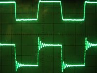
I've enclosed a photo shot of the typical wild 1st stage without anode snubber compensation with considerable ringing and the other with a near optimised squarewave form with a typ R/C arrangement.
From the amount of ringing there isn't much stability left and a flighty 18dB/octave crossover might just aggravate oscillation on peak signals. It all depends on the o/p tranny quality.
Dealing with this awkward waveform can come in another post.
Bear this in mind; to your feedback potty, you might notice that with less global nfb, if you hear some amp noise in JbL's, then you definitely hear this (double) in the Klipsch's. So may be best stay at 20dB.The objective is to use a fixed value resistor for the global nfb; ..- reiterate the ratio's til you arrive at say 20dB feedback- then measure/jot the value with Ohmmeter.
I don't know what Osprey thinks; I'm personally against variable global feedback pots as they can play havoc with the response.
4 stage amps using 20dB global nfb will show roughly -65dB to -75dB down signal/noise ratio, i.e you will just hear this with ear pricked into LS.
If you master all this, then you getting ahead.
richy
By coicidence I've a 25 watt amp ducked-up on the bench sim to yours but a different o/p tranny and front end. The principle problem is the same for all amps. There is a more scientific approach to setting up feedback amps and the reason is to extract the best performance from them.
I've enclosed a photo shot of the typical wild 1st stage without anode snubber compensation with considerable ringing and the other with a near optimised squarewave form with a typ R/C arrangement.
From the amount of ringing there isn't much stability left and a flighty 18dB/octave crossover might just aggravate oscillation on peak signals. It all depends on the o/p tranny quality.
Dealing with this awkward waveform can come in another post.
Bear this in mind; to your feedback potty, you might notice that with less global nfb, if you hear some amp noise in JbL's, then you definitely hear this (double) in the Klipsch's. So may be best stay at 20dB.The objective is to use a fixed value resistor for the global nfb; ..- reiterate the ratio's til you arrive at say 20dB feedback- then measure/jot the value with Ohmmeter.
I don't know what Osprey thinks; I'm personally against variable global feedback pots as they can play havoc with the response.
4 stage amps using 20dB global nfb will show roughly -65dB to -75dB down signal/noise ratio, i.e you will just hear this with ear pricked into LS.
If you master all this, then you getting ahead.
richy
Attachments
So to adjust this, do I simply install a pot and twist away with a screwdriver "'til it sounds good," or is there a more objective, "scientific" approach to feedback adjustment?
Well, why not? You know you have the "stop" in there at 24db with your 10k resistor so you can put your 25k in series and dial in what you like.
OTOH We know that with Vout, no nfb = 2.910 V then .29V corresponding to 20 db you can dial in 20 dB exactly and know how it sounds. Listen for a while and dial in 12dB and see what that sounds like. 12dB would be .725V out. You have efficient speakers so you can even try 6dB or 1.5V out.
In the end you need negative feedback to lower the output impedance. Negative feedback does wonders but it also exacts a price; there is no free lunch. Amps without NFB can have an immediacy not present in many amps with heavy NFB. This translates into dynamics. And part of the allure of really efficient speakers are the effortless dynamics.
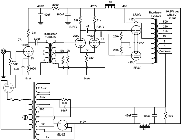
The only way to get rid of the NFB is to remove the 6550s and install 2A3s, 6B4s or 6A5s. You would need a new filament transformer for each of these triodes, the center tap goes to ground through a 800 ohm resistor. Triodes give you a lower output impedance over beam tubes and pentodes and that translates into less need for NFB.
Here's the amp I am working on now, notice how you could slap the Williamson FE on instead of the transformer and you'd have a Williamson Triode amp:
Zman3,
You have received some good advice and discussion; mine come a bit late, but a few points if I may:
No.
One sets the NFB to achieve a certain distortion goal and in an existing amplifier, to leave a comfortable margin of stability.
The problem of adjusting by hearing is that very little audible effect (except change in volume level) is going to take place in a short span of time. I fear I am not a fan of setting a mystical amount of 'optimal NFB' by ear, either side of which sound allegedly 'deteriorates'. That is a myth. If such a situation comes over as audible, the design is flawed, or NFB stability either side of such a setting is compromised. This changes as the amount of NFB is changed - one cannot simply turn a feedback pot without adjusting other things for each setting.
Ideally one wants as much NFB as the design will take, because distortion is inversely related to NFB. One sets the stability as suggested, mainly by RichW, using his oscillograms as indication.
A few further points:
1. The purpose of the 470K resistors in parallel with the final 0.25 uF capacitors has not been fully explained. The l.f. stability of this type of circuit has been in question. As l.f. phase shift increases as result of the reactance of the 0.25 uFs as frequency decreases, stability is threatened with all the other similar phase shifts. A resistor across the 0,25uF will cause that component's contribution, to shift back to zero at a very low frequency where the reactance of the capacitor becomes larger than 470K. I presume that someone has built and tested the present circuit before publication and found the resistors necessary, therefore I will leave them in.
2. I am not sure what the 220 ohm resistors are doing in the driver cathode circuits - they were not in the original Williamson. They cause some degeneration which is disadvantageous in this type of driver as it increases the internal triode impedance (although in this circuit it is very small). I would leave them out, just keeping the common 470 ohm. (The original Williamson used 390 ohm.)
3. More serious is having to use 47K grid resistors for the final stage. The Williamson used 100K, but that was for cathode bias. Unfortunately fixed bias necessitates the use of a lower grid resistor. Such a low value effectively in parallel with the anode 47Ks increases distortion somewhat, especially at high output.
You use KT88s. The min. grid resistor spec. for them is 100K, and I would suggest increasing the grid resistors to 100K. Do not expect to immediately hear a difference, but every bit helps.
4. Then it sounds very pious to indicate matched 47K driver anode resistors but not so for the KT88 grid resistors! They are in parallel with the anode loads. Furthermore a balance setting off centre at the bias pot will make them unequal and thus so for the total driver load. If one is perfectionistic one should include a say 5K pot where the h.t. feeds the 47Ks for perfect adjustment of signal to the power amplifiers. But all that may not make a lot of practical difference; just to make the point about matching some things and not others.
I have carried on for too long. Hope some of this was of interest; all success with your project.
You have received some good advice and discussion; mine come a bit late, but a few points if I may:
zman3 said:So to adjust this, do I simply install a pot and twist away with a screwdriver "'til it sounds good," or is there a more objective, "scientific" approach to feedback adjustment?
No.
One sets the NFB to achieve a certain distortion goal and in an existing amplifier, to leave a comfortable margin of stability.
The problem of adjusting by hearing is that very little audible effect (except change in volume level) is going to take place in a short span of time. I fear I am not a fan of setting a mystical amount of 'optimal NFB' by ear, either side of which sound allegedly 'deteriorates'. That is a myth. If such a situation comes over as audible, the design is flawed, or NFB stability either side of such a setting is compromised. This changes as the amount of NFB is changed - one cannot simply turn a feedback pot without adjusting other things for each setting.
Ideally one wants as much NFB as the design will take, because distortion is inversely related to NFB. One sets the stability as suggested, mainly by RichW, using his oscillograms as indication.
A few further points:
1. The purpose of the 470K resistors in parallel with the final 0.25 uF capacitors has not been fully explained. The l.f. stability of this type of circuit has been in question. As l.f. phase shift increases as result of the reactance of the 0.25 uFs as frequency decreases, stability is threatened with all the other similar phase shifts. A resistor across the 0,25uF will cause that component's contribution, to shift back to zero at a very low frequency where the reactance of the capacitor becomes larger than 470K. I presume that someone has built and tested the present circuit before publication and found the resistors necessary, therefore I will leave them in.
2. I am not sure what the 220 ohm resistors are doing in the driver cathode circuits - they were not in the original Williamson. They cause some degeneration which is disadvantageous in this type of driver as it increases the internal triode impedance (although in this circuit it is very small). I would leave them out, just keeping the common 470 ohm. (The original Williamson used 390 ohm.)
3. More serious is having to use 47K grid resistors for the final stage. The Williamson used 100K, but that was for cathode bias. Unfortunately fixed bias necessitates the use of a lower grid resistor. Such a low value effectively in parallel with the anode 47Ks increases distortion somewhat, especially at high output.
You use KT88s. The min. grid resistor spec. for them is 100K, and I would suggest increasing the grid resistors to 100K. Do not expect to immediately hear a difference, but every bit helps.
4. Then it sounds very pious to indicate matched 47K driver anode resistors but not so for the KT88 grid resistors! They are in parallel with the anode loads. Furthermore a balance setting off centre at the bias pot will make them unequal and thus so for the total driver load. If one is perfectionistic one should include a say 5K pot where the h.t. feeds the 47Ks for perfect adjustment of signal to the power amplifiers. But all that may not make a lot of practical difference; just to make the point about matching some things and not others.
I have carried on for too long. Hope some of this was of interest; all success with your project.
Osprey: I noticed the resemblance of your current amp to the Williamson circuit right away; I hope it's behaving itself on the bench and that it sounds good, too. Please post pics of the finished product; I'd really like to see it.
Johan: I appreciate your input, too. I goofed on that last copy of the schematic; I forgot to erase those 220 ohm cathode resistors in the driver stage! Only the 470 ohm remains. As for the output tubes, I actually intend to run a pair of NOS Tung-Sol 6550's in the final product. I'm just using the relatively cheap KT88's until I get the "kinks" worked out of the circuit.
You're also right about the audible differences between various feedback levels. Personally, I can hear none, except for when no feedback is applied at all; the highs sound more open and "airy", but the lower frequencies sound rather flabby and uncontrolled.
There is another version of this Acrosound circuit showing 100k cathode resistors in the output stage and 1 Meg resistors across the 0.25 uF coupling caps. I may try this combination.
I'm having lots o' fun in the meantime though!
.... and I had better clear up a possible misconception!
This is ambiguous. By 'this type of circuit' I meant the Williamson topology in general, not particularly one including those 470Ks. That rather is a solution, as explained!
Regards
Johan Potgieter said:
1. The purpose of the 470K resistors in parallel with the final 0.25 uF capacitors has not been fully explained. The l.f. stability of this type of circuit has been in question.
This is ambiguous. By 'this type of circuit' I meant the Williamson topology in general, not particularly one including those 470Ks. That rather is a solution, as explained!
Regards
- Status
- This old topic is closed. If you want to reopen this topic, contact a moderator using the "Report Post" button.
- Home
- Amplifiers
- Tubes / Valves
- 6550 Williamson - Low Bass Response...