What you may not see in a sim is that with a lowish value of this R18 you get a LOT more power on signal peaks, the amp just sounds a lot more powerful.
Hi Allen,
This was already understood as, as I see it , at peaks the lower value of R18 makes the amp able to partly approach Class-AB. But maybe there is another explanation?
Hi 45,
Please check the edit in my previous post.
You ground cathodes through a small value linear pot (in this case 50 ohms should be enough), then once you get the best dynamic balance (i.e. minimum distortion) you measure the values on the pot and replace it with fixed resistors.
You forgot to say minimum EVEN order distortion
") .
.Single ended input + direct coupled (or RC-coupled) cathodyne which drives the output.
Sorry, as you mentioned ECC40 and to use it at the input instead of tranny I missunderstood.
Think the Concertina with ECL82 should be biased to ca 60V with 30k resistors at 250V to be in its best area. So probably 3 caps will be needed.
revintage said:
Edit: Added curves to show what happens with 300V/5k/25mA. Pmax=7W, Pclass-A=1W. Also from 1W and upwards the tubes are over Pamax with 16W at clipping. These are very course figures, just an indication.
Those are not the right curves to use for push-pull operation. If you want to have a better idea you should rather use the composite curves.
The tube is not dissipating 16W because you have to subtract the output power which is delivered to the load. Also for 7W output and conventional biasing (i.e. self bias or fixed bias by means of large grid resistors) the grid current will drive tube to increase the negative bias to "protect" itself. Basically the quiescient bias is modulated!
With a typical 10 microampere DC grid current (which occurs when the bias is still negative) through 220K grid resistor you get 2.2V bias change!
Now, that amp is 5W for me.
7W is really clipping and I don't think you will listen to the amp at this level, except maybe for some sporadic transient where at most you will notice that the amp is at its limit and/or distortion is too much. In that case you just turn down the volume pot and everything will be fine.
Cheers,
45
revintage said:
Think the Concertina with ECL82 should be biased to ca 60V with 30k resistors at 250V to be in its best area. So probably 3 caps will be needed.
No, revintage. The ECC40 would the choice for the EL84 PP.
Cheers,
45
Those are not the right curves to use for push-pull operation. If you want to have a better idea you should rather use the composite curves.
They are working allright. No need for composite, but prove me I am wrong by showing
! Could be I am wrong about Pd. Will anyway doublecheck with Tubecads TCJ PP Calculator when I get home.Please check in at http://www.turneraudio.com.au/loadmatch3-pp-triodes.html . My [url]www.revintage.se/PPABAMP.xls as used is built on this.
Sent a mail concerning 6S4S. Would be interesting to have your opinion.
The links went wrong !
!
My spreadsheet:
www.revintage.se/PPAMP.xls
Based on:
www.turneraudio.com.au/loadmatch3-pp-triodes.html
and
http://www.turneraudio.com.au/loadmatch4-pp-beamtetrodes.html
!My spreadsheet:
www.revintage.se/PPAMP.xls
Based on:
www.turneraudio.com.au/loadmatch3-pp-triodes.html
and
http://www.turneraudio.com.au/loadmatch4-pp-beamtetrodes.html
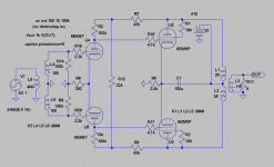
Input transformers are not a source of distortion if implemented correctly. In this specification I advised a step down which eliminates almost all areas of potential distortion. In addition to this loading the secondaries adequately eliminates peaking. The Use of an input transformer in this application was partly to use the microphone transformers I had (very good quality) and partly to allow for the common grid leak bias - which works far better than anyone would believe. The step down is essential in this case to prevent overloading the grid of the triode which will only bias up to -0.8V or so. Grid leak needs a bit of headroom, but the LTP should help correct for slight overload.
It will also help a little correcting for imperfections in the LTP.
It also allows you to use an easy to generate negative rail which can allow direct coupling of driver to output. All in all it allows for a lot of flexability.
It was a design choice and not a random decision to include the input transformer. Others may make other choices.
In my main amp I use a mains toroidal as an input phase splitter with a voltage step down of about 4:1+1. This is cheap and works without a hitch with correct loading. Run as a 1:1+1 would not work in this situation. I have a -300V negative rail that the front end LTP hangs off, this has allowed a direct coupled partial feedback amp with no caps in the signal path - apart from the cathode bypass of the outputs.
For me the main issue with getting the ECL82 design right, was not overloading the grids of the triodes whilst allowing adequate current to allow the partial feedback to work. This is a tough balancing act with the triode of the ECL82. I'm not certain any of the suggestions so far have bettered it.
Shoog
Shoog said:I'm not certain any of the suggestions so far have bettered it.
Shoog
The transformer can be a must in your case but not if you use a simple cathodyne splitter where there is no problem at all with overloading.
Rather it looks to me as a remedy to a deficiency of that topology, at least using those tubes!
The single ended input + cathodyne gives two perfect identical signals well above the limit of the output transformer usually, if good used. This is true in general, in fact there were many radio-frenquency amps that used such splitter.....
The unbalance can only come from the output where there is a solution to balance it alone, even using the cathodyne. This is not effective in your case, where the output tubes are self-biased.
45
The unbalance can only come from the output where there is a solution to balance it alone, even using the cathodyne. This is not effective in your case, where the output tubes are self-biased. 45
I always try to design all of my projects to need zero adjustment over time or at setup and again this has influenced the output stage design.
Also the use of a cathodyne either you need an additional driver stage, or cannot be used with partial feedback. Having used partial feedback and found it superior to global feedback - this would be a major problem in a design where the outputs are run as pentodes.
Shoog
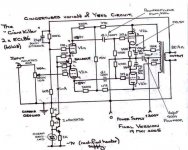
What about NO caps? Without C1 pure Class-A 3W, with C1 a little more!
If using a mains toroid as OPT, R6 maybe could be substituted for two CCSs(and a cap between the cathodes) to balance the output stage.
R5 will dissipate close to 10W.
Heaters should be lifted to ca 50V.
If using a mains toroid as OPT, R6 maybe could be substituted for two CCSs(and a cap between the cathodes) to balance the output stage.
R5 will dissipate close to 10W.
Heaters should be lifted to ca 50V.
Attachments
Thats very similar to my main amp. The only thing I don't like is all that wasted heat in R5, I would prefer to run a neg rail and extend the front end tail by about a 100V. This is much less wasteful of power but needs a simple little negative supply (can be very small - my version has a choke and two filter stages and still only takes up a 4"x4" board).
Remember its extremely easy to place the cathodes and grids at any potential using an input transformer - which allows many things not easily achieved without it.
Shoog
Remember its extremely easy to place the cathodes and grids at any potential using an input transformer - which allows many things not easily achieved without it.
Shoog
Shoog said:
I always try to design all of my projects to need zero adjustment over time or at setup and again this has influenced the output stage design.
Also the use of a cathodyne either you need an additional driver stage, or cannot be used with partial feedback. Having used partial feedback and found it superior to global feedback - this would be a major problem in a design where the outputs are run as pentodes.
Shoog
Actually the discussion shifted towards triode connection for the output stage in the last posts. The power output will be around 4W before the start of the clipping, where the input stage has still enough headroom and thus will not sound harsh at all, IMO.
Anyway, in the case of pentode connection the additional driver brings a substantial increase of power: 10 clean watts!
45
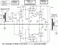
can you just remind me what purpose the R12 performs in your design. Does it help in balance.
Hi Shoog,
Stole it from Yves. As I see it it´s for getting the right amount of feedback. Infinite resistor=full feedback, shorted resistor no feedback.
Did a few sims. There seems be a problem! With more feedback the input stage clips/distorts earlier. Also 3H gets higher relative H2 with more NFB!?
Shoog,
If I may answer for Lars - R12 in the original Baby Huey set the local feedback amount - see the cross-coupled 15K in the original baby Huey schematic attached. It was varied to tune the amount of local feedback applied (about 6DB extended the top & bottom ends by an octave) versus the amount of global feedback.
AFAIK, this was the magic in Yves/Gingertubes Baby Huey circuit? But maybe Gingertube can explain more
I don't believe you have anything similar in your Tabor clone or do you?
Edit: Oops cross posted with Lars
Attachments
revintage said:
Did a few sims. There seems be a problem! With more feedback the input stage clips/distorts earlier. Also 3H gets higher relative H2 with more NFB!?
This is as expected. The feedback anode-anode presents a much lower impedance load to othe driver tube resulting in a steeper load-line. This will limit possible feedback that can be applied before driver distortion becomes excessive.
I showed some loadlines in this post
SveinB.
Thanks Svein!
What comes to mind when using triode-strapping is that absolutely no NFB, being local or global, is needed.
I got blinded of the nice "one connecting point to the PSU" idea. This can of course still be done by shorting R12.
If we now use the ECL82s as example and find sensitivity to high a good stepdown transformer should be used instead.
The main concern should be to choose a working point with as low 3H as possible. Unfortunately this also will give us a lower Pout.
If wanting lower Zout(and lower gain) from the driver triodes, local feedback could eventually be used by connecting them as anode followers. But serial resistance is no fun !
!
What comes to mind when using triode-strapping is that absolutely no NFB, being local or global, is needed.
I got blinded of the nice "one connecting point to the PSU" idea
. This can of course still be done by shorting R12.If we now use the ECL82s as example and find sensitivity to high a good stepdown transformer should be used instead.
The main concern should be to choose a working point with as low 3H as possible. Unfortunately this also will give us a lower Pout.
If wanting lower Zout(and lower gain) from the driver triodes, local feedback could eventually be used by connecting them as anode followers. But serial resistance is no fun
!
I don't believe you have anything similar in your Tabor clone or do you?
No John. Have have to admit that I'm very much a suck it and see man myself. The exact details of partial feedback are a bit mind numbing. I have my own ideas, but I'm not c ertain they are perfect. It does work though.
Did a few sims. There seems be a problem! With more feedback the input stage clips/distorts earlier. Also 3H gets higher relative H2 with more NFB!?
It doesn't surprise me unduly. The more feedback, the more drive needed to reach the same levels, and the more chance of that dreaded driver grid overload which I keep warning about !!
This uses also 2 holes in the chassis. I suspect it sounds good because I am now listening to this topology with el84 (and 2sk30 in input). Just to keep the discussion going
I suspect it won't sound as good, though it may deliver more cleaner power. No partial feedback, and an extra stage - which just happens to be a nasty cathode follower which never sound right.
When dealing with valves like the ECL82 you have to know their limitations and work with them. For me the puny sub 5W power is not a limitation sinced my speaker are happy with 2watts and my headphones need less than one - but for you Jaap I suspect it may be a wall.
Shoog

- Status
- This old topic is closed. If you want to reopen this topic, contact a moderator using the "Report Post" button.
- Home
- Amplifiers
- Tubes / Valves
- Could this become a Baby Huey killer ?