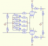
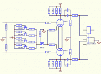
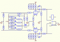
I'm thinking of building a current-source biased LTP line stage, to convert from SE to balanced and drive my electrocompaniet clone amp. What are your experiences with regards to the sound of this topology, also keeping in mind that it has to be done on the cheap?
Cheers.
Cheers.
Attachments
From simulation it seems that gain balance in the two outputs requires an almost ideal current source. Even a current source impedance of 20K, which in practice does not seem easily attainable, leads to an amplitude imbalance as high as 0.5dB. The JFET current source has an even lower impedance. Any thoughts would be greatly appreciated...
dw8083 said:If I could tag a similar question to the thread:
Are there good low power class A amp designs that have balanced input rather than using RCA with a phase splitter in the amp?
-David
Are you looking for a push-pull or single ended amp? With a balanced input, your phase inversion has been done for you, and that is quite nice. For low power single ended amplifiers, this doesn't offer you a whole lot of favors (I still tend to build in a transformer coupled XLR jack onto my SE amplifiers).
Thanks EC8010. I too saw the need for a negative supply when I started simulating possible topologies.
The cascode CCS you suggest seems to work very well; only 0.03dB differential imbalance is produced. But out of pseudoscience or just biased intuition, I was thinking of not using bipolar transistors in this design. Mosfets and jfets connected as simple CSs do not yield the required impedance. I'm thinking of cascoding a jfet and a mosfet.
Cheers.
I built such a preamp to drive the Pass F4 in balanced (The "ImPasse") and demo'd it at BAF '07. It can also be used to drive a balanced input of a power amp. The article was accepted by AudioXpress, but they've been sitting on it for nearly a year; we'll be posting it on diyAudio shortly. It will accept both single ended and balanced sources, and has a balanced output. Max gain of 20dB, with THD at under 0.05% at 20V out.
audiowize said:
Are you looking for a push-pull or single ended amp? With a balanced input, your phase inversion has been done for you, and that is quite nice. For low power single ended amplifiers, this doesn't offer you a whole lot of favors (I still tend to build in a transformer coupled XLR jack onto my SE amplifiers).
I'm looking for a single ended balanced input amp. Although a good push-pull design would be OK. All my sources are balanced, seems a shame not to leverage them in balanced mode.
-David
Why have all those expensive FETs down the bottom? The bipolar transistor rules OK. You might do better to hold the gate of the upper FET at a negative voltage so as to increase Vds and avoid some of the "tetrode" negative resistance problems sometimes seen at low Vds with high voltage FETs.
I'd ideally like to see more voltage across that upper FET and less across the lower. The lower ones only need 5V or so. The capacitor looks fine, but it doesn't need to be so big. FETs are high impedance devices - scale those resistors up by a factor of 20 and scale the capacitor down by a factor of 20.
Will do, cheers. A smaller mosfet with less capacitance helps push the CMR 1st order pole up, so a IRF820 will help here.
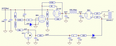
I ordered the 6N6s too dirt cheap, so the design will be on its way soon. I need to get the regulated tube power supply design right, as the power supply rejection of the LTP is virtually nil.
I ordered the 6N6s too dirt cheap, so the design will be on its way soon. I need to get the regulated tube power supply design right, as the power supply rejection of the LTP is virtually nil.
hollow_man said:TThe cascode CCS you suggest seems to work very well; only 0.03dB differential imbalance is produced. But out of pseudoscience or just biased intuition, I was thinking of not using bipolar transistors in this design.
Cascoded BJTs make excellent active tail loads for LTPs. I've done a couple of projects already and used cascoded BJTs for active tail loads in both. They definitely do a good job here. Put enough voltage across them, and any sort of "varactor" effects become unimportant. AC balance is excellent, and they sound very good too.
- Status
- This old topic is closed. If you want to reopen this topic, contact a moderator using the "Report Post" button.
- Home
- Amplifiers
- Tubes / Valves
- SE to Balanced tube preamp idea
