I'm not sure about your power supply. You've used a negative reference to avoid it having to be in the error amplifier's cathode, and that's a nice idea, but you haven't filtered the HF noise from the reference and the speed-up capacitor from the sampled HT looks rather large. You might want to have a more detailed think about those arrangements.
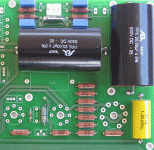
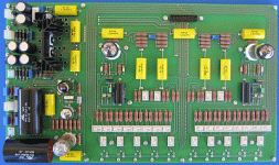
Thanks EC8010, I have since revised the schematic in an attempt to play safer. This is what I have implemented on the pcb.
Loop gain will be reduced due to degeneration of the error amplifier, hence regulation will be poorer, but hopefully adequate for my widely fluctuating mains supply.
Loop gain will be reduced due to degeneration of the error amplifier, hence regulation will be poorer, but hopefully adequate for my widely fluctuating mains supply.
Attachments
There's nothing complicated about neon filtering. You can't put large capacitors across neons (would make them oscillate), but you can take the neon voltage via an RC network into your (highish impedance) summing node. So, you might be able to get away with a 100k resistor from the neon, then add a 1uF to ground. That gives you a lot of filtering of neon noise.
I was not aware of the terminology. Definitely, supplying the reference voltage to the high-Z control grid rather than the cathode permits this type of filtering. So apart from better regulation, lower noise would also be expected of the first topology; but how much better, I haven't a clue. And the second circuit is quite popular too.
Attachments
hollow_man said:So apart from better regulation, lower noise would also be expected of the first topology; but how much better, I haven't a clue. And the second circuit is quite popular too.
Noise from the reference is the major source of noise in a regulator. The second circuit is popular because it is cheap (oh, and lots of people know about it).
Slowly getting together...
http://www.imageshack.gr/view.php?file=jddsyil3x28d9obtn9y0.gif
http://www.imageshack.gr/view.php?file=jddsyil3x28d9obtn9y0.gif
http://www.imageshack.gr/view.php?file=jddsyil3x28d9obtn9y0.gif
http://www.imageshack.gr/view.php?file=jddsyil3x28d9obtn9y0.gif
Attachments
Got the transformer and hooked it up last night - power dissipation is high, but on the bench (with signal generator and scope) all seems ok. What really surprised me though, is how quite the regulated 280V are. While I get about 10mVp-p from the filament's LM317 regulator, there is no more that 3mV of noise on the 280V. True there is the typical of tubes low-frequency wander, but its amplitude is less than 10mVp-p. All in all, this is an excellent tube regulator topology, so much that fancier circuits may not have much more to offer.
Too much cascode is bad for your health
I see people are still interested in this thread. I have listened to the prototype for quite a while now and this is what I have to say:
Never mind the simulations or sonically unrelated technical justifications; BEWARE of cascode current sources, either BJT or mosfet, at least for long-tailed pairs. Would you believe that the thing measured f3dB 300KHz but sounded more like 5KHz?
Oh and do bear in mind that with LTPs you are listening to the current source and its power supply, not the amplifying devices themselves.
No wonder clever people are suspicious of the topology.
Re: Too much cascode is bad for your health
Once you start listening you notice such "discrepancies" all the time. Still, i'm curious why you blame the CCS. I use a similar circuit with a single fet ccs and a Jung reg for the negative voltage and it sounds quite ok. Maybe your high voltage reg carries some of the blame. Or the passive parts.
hollow_man said:Would you believe that the thing measured f3dB 300KHz but sounded more like 5KHz?
Once you start listening you notice such "discrepancies" all the time. Still, i'm curious why you blame the CCS. I use a similar circuit with a single fet ccs and a Jung reg for the negative voltage and it sounds quite ok. Maybe your high voltage reg carries some of the blame. Or the passive parts.
I didn't think it was possible too, but hooking up two windings erroneously, so that -ve bias was much reduced, more high frequency content was restored. The reduced voltage meant that the JFETs operated in their resistive region, i.e. bye-bye to the cascode.Still, i'm curious why you blame the CCS
Then I changed into a different CCS topology, as used by Nelson, and all the high frequencies reappeared. But the sound still was unconvincing so if the ccs had such a dominant effect next was its power supply. Out with the LM337 and replaced it with a discrete, no feedback regulator and there was marked improvement. Initially I thought I cracked it, but further listening left me unimpressed. The low frequencies may be excellent and the soundstage very precise, but realism in mid to high frequencies is just not up to expectations. Transistor sound.
With regards to passive components, resistors are all Dale RN-65 and capacitors low-inductance metalized polypropylene. There are no electrolytics anywhere but the filament voltage regulators. Maybe the 6H6Ps are just cr@p, so a pair of 6H30Ps is on its way. BAT and Conrad Johnson must know something about that!
In the meantime, its back with the old nice and simple SE passive preamp.
hollow_man said:
Transistor sound.
Thanks for the explicit reply. My build also has some of the "transistor sound" although the bass is very nice indeed.
- Status
- This old topic is closed. If you want to reopen this topic, contact a moderator using the "Report Post" button.
- Home
- Amplifiers
- Tubes / Valves
- SE to Balanced tube preamp idea


