Well, time has come for me to start my own Tubelab.com Simple SE build thread. I ordered the board earlier this morning and George has already replied saying the board has shipped. How's that for customer service on a Saturday?
I've also ordered transformers, tubes, and most of the other components. I'm going to be running the following:
Hammond 374BX Power Transformer
Hammond 193D 8H, 150ma Choke
Edcor CXSE25-8-5K OPT's
ASC Metal Poly "Motor Run" Cap, 50 uF 440VAC
Tubes:
EH KT88's - Have a pair of cheap EL34's for initial "smoke testing"
EH 12AT7
Chinese GZ34/5AR4
More later, I'm sure. 😎
I think you may have under specified your choke. KT88s are going to pull almost 80mA each if you use the recommended 560R cathode resistor. From memory, the constant current source for the 12AT7 is running around 10mA per side. That is going to be around 180mA total. Your choke is rated at 8H 150mA. Inductance will reduce with increasing current. Why not use a 193H 5H 200mA or 193J 10H 200mA?
80uF 500VAC motor run caps here foe $12. Work well, have used them several times.
Good luck with the project!
Chris
80uF 500VAC motor run caps here foe $12. Work well, have used them several times.
Good luck with the project!
Chris
chrish said:I think you may have under specified your choke. KT88s are going to pull almost 80mA each if you use the recommended 560R cathode resistor. From memory, the constant current source for the 12AT7 is running around 10mA per side. That is going to be around 180mA total. Your choke is rated at 8H 150mA. Inductance will reduce with increasing current. Why not use a 193H 5H 200mA or 193J 10H 200mA?
Hmm, good point. You are probably right. Guess I better email AES to change my order before they ship.

Thanks for the link Chris. Shipping @ $12.45 seems a bit much though. It can't weigh more than a pound, USPS tells me $4.80 from them to me. I already have the 50 uF, 440VAC unit I'll use for now. It can handle much more in DC voltage.
Hi N1ESE, George replied to me too, my pcb's are on their way to Greece ....
have allready orderd from digikey the parts list and I'm trying to decide the transformers/choke combo
so far it looks like the 374BX is gonna be the power, the 193J the choke and probably the 1628 the output
good luck with ypur project ....
have allready orderd from digikey the parts list and I'm trying to decide the transformers/choke combo
so far it looks like the 374BX is gonna be the power, the 193J the choke and probably the 1628 the output
good luck with ypur project ....
That's great jimazz. I've ordered everything except for my Edcor CXSE outputs. I have to call them first thing Monday morning to place my order. You should like the 1628SEA's if you go with them. I know George really likes those. 😎
You should like the 1628SEA's if you go with them. I know George really likes those.
After having some extended listening time with both transformers I like the Edcor CXSE's better than the Hammonds. The high frequency response is better on the Edcors. When auditioned on efficient speakers where the average power is low there is clarity and detail on the Edcors that just isn't there on the Hammonds. The Edcor is a more efficient transformer as well allowing slightly more power from the same amplifier as the Hammond. When cranked to the max the Hammonds have better bass and less distortion, but how often do you listen this way?
You think that the Edcor CXSE25-8-5K OPT's should be better with the 374BX for the simple se , with 8ohm speakers ?? What about 6ohm??
I see edcor has a dealer in Europe (Belgium), so I must mail them for info ....
I see edcor has a dealer in Europe (Belgium), so I must mail them for info ....
tubelab.com said:When cranked to the max the Hammonds have better bass and less distortion, but how often do you listen this way?
I hardly ever listen that way. I usually turn it up till it explodes - then back up just a little.

Dumb Question #1 - Should I use shielded twisted pair between the volume pot and the circuit board and RCA jacks?
N1ESE said:Dumb Question #1 - Should I use shielded twisted pair between the volume pot and the circuit board and RCA jacks?
It's hardly a bad idea and I don't see how it can hurt. I know I'll be using shielded wire from at least the inputs to the pot since there's no room in my chassis to use an extension shaft to shorten the signal path.
I used to put shielded wire in between the input jacks and the "signal in" connections on the circuit boards. I did this on a couple of amplifiers, and I think these guys have a slight rolloff on the top end. I wonder if the shield acts as a small value cap in parallel with the wire. Ground one end of the shield, and you might end shorting some high frequency content to ground.
I've since started using just plain unshielded hookup wire and keeping the runs as short as possible. I've noticed improved high frequency response in my recent builds. I need to go back and rework my older amplifiers to finally prove my theory.
I've since started using just plain unshielded hookup wire and keeping the runs as short as possible. I've noticed improved high frequency response in my recent builds. I need to go back and rework my older amplifiers to finally prove my theory.
Ty_Bower said:I used to put shielded wire in between the input jacks and the "signal in" connections on the circuit boards. I did this on a couple of amplifiers, and I think these guys have a slight rolloff on the top end. I wonder if the shield acts as a small value cap in parallel with the wire. Ground one end of the shield, and you might end shorting some high frequency content to ground.
Yeah, I was wondering a bit about this phenomenon as I've experienced similar stray capacitance with some low power solid-state amplifiers for radio use in the past.
This is primarily going to be hooked up to my iPod and/or computer. I'm just going to put the input connector, 1/8th-inch stereo jack, on the front panel near the pot. Eventually, I will add an input switch and second RCA inputs on the back.
Can you elaborate on this Ty? The way that I've always been taught to use the shield in shielded wire is to ground only one end of the shield and float the other. I don't see, in that case, how the shield could be in parallel with anything acting as a capacitor. And if this were the case, wouldn't you think that people would complain a lot more about shielded IC's since they would tend to behave in exactly the same manner? And wouldn't the signal loss be measurable if it's audible? But my skills lie on the fabrication side of these things, not the technical, so it's quite possible I'm just not seeing it correctly.Ty_Bower said:I wonder if the shield acts as a small value cap in parallel with the wire. Ground one end of the shield, and you might end shorting some high frequency content to ground.
n_maher said:Can you elaborate on this Ty?
I wish I could. I'm probably hooking up the shielded wire wrong. All I know is my amps with shielded wire on the inputs are just a little too soft on the top end. The amps where I use just plain hookup wire sound fine. I keep the runs short (two inches or less, usually) and I haven't had problems. It's not like these are phono level signals anyway.
Maybe I did something dumb like use single conductor shielded wire, and I had to use the shield as the ground conductor? I dunno. As I said, some day I need to go back to those amps and figure it out.
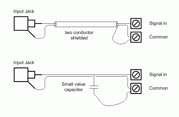
Ok, how's this?

On the top I've got a two conductor, shielded hookup cable. The shield is grounded at only one end. Isn't the shield effectively one plate of a capacitor, and the conductor is the other plate? Are my two drawings electrically equivalent?

On the top I've got a two conductor, shielded hookup cable. The shield is grounded at only one end. Isn't the shield effectively one plate of a capacitor, and the conductor is the other plate? Are my two drawings electrically equivalent?
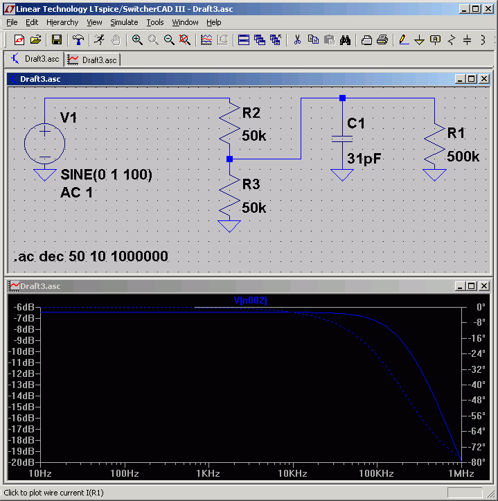
The capacitance value of quality cable should be specified. It's 31 pF/foot in the case of RG-174/U.
For the run from the input jacks, I have used some crummy "shielded" audio cable that had only about 10% shield coverage, and RG-174/U with about 87% shield, and can't hear any difference, which is to be expected, I guess, since the interconnects running to the amp are just unshielded parallel conductors, of who knows what specification.
I only ground the shield at one end and in the Simple SE, that is at the pcb. Whether it's audio or RF, grounding both ends of a shielded cable invites a ground loop.
Win W5JAG
- Status
- Not open for further replies.
- Home
- More Vendors...
- Tubelab
- YASSE - Yet Another Simple SE Build
