dc-coupled zip
Hello Michael,
thank you very much for your interest in the "fourth circuit topology".
Do you have the update_1.May_2007 ... zip from the vintage repair and discussion forum?
It contains the ECC83 PCL85 dc coupled line pre schematic.
Kind regards,
Darius")
Originally #23 posted by Michael Koster
#22
"I think the attachments from this thread
are interesting for you."
Very interesting. The signal path outlined in red helps a lot
...
Michael
Hello Michael,
thank you very much for your interest in the "fourth circuit topology".
Do you have the update_1.May_2007 ... zip from the vintage repair and discussion forum?
It contains the ECC83 PCL85 dc coupled line pre schematic.
Kind regards,
Darius
Re: #29 #32
How far off the 1/µ mark did it land? (With your 6080?)
And the overall cascode? How far from 1?
----------------------------------------------------
What constitutes 'special construction'?
I was kinda leaning towards 6N30Pi,
especially for a smaller tube.
----------------------------------------------------
I was never too certain the Mu of the lower
triode as it is not driving constant current,
but sees the same current as the top tube.
A transformed (4th circuit) load resistance?
oldeurope said:
How far off the 1/µ mark did it land? (With your 6080?)
And the overall cascode? How far from 1?
----------------------------------------------------
What constitutes 'special construction'?
I was kinda leaning towards 6N30Pi,
especially for a smaller tube.
----------------------------------------------------
I was never too certain the Mu of the lower
triode as it is not driving constant current,
but sees the same current as the top tube.
A transformed (4th circuit) load resistance?
#24 #25 #42
oh oh, Wavebourn,
loading down a triode is a very bad design.
It disappoints me to hear something like this from you.
Have a look at post #12 and click on the hyper link
well known factor. Hope it helps ...
Hi Jon,
See the advantages listed in #12.
The plate followers impedance depends in the impedance
of the feedback loop and I don't like feedback.
The unity µ triode stage see post #6 has no feedback
thus the input resistance is not reduced by negative
voltage feedback like it is in a so called plate follower.
BTW Look at this list, funny isn't it?
Hello kenpeter
I tested some ECC82. I didn't write down the results,
it was some weeks ago.
See post #12
From the graph I get µ'= 0,15 @ Ia'=100mA, Ug'=-10V for the 6080.
Thus in this example you should expect something ≈ 0,3.
I don't know this tube.
A transformed constant current source is still a constant current source.
Kind regards,
Darius
Originally #24 posted by Wavebourn
Take any tube and select load resistance and idle current to get exactly unity gain. No feedback, the problem solved.
oh oh, Wavebourn,
loading down a triode is a very bad design.
It disappoints me to hear something like this from you.
Have a look at post #12 and click on the hyper link
well known factor. Hope it helps ...
Originally #25 posted by jon_010101
So true! -- I would wire up a unity-gain plate follower and call it a day
Hi Jon,
See the advantages listed in #12.
The plate followers impedance depends in the impedance
of the feedback loop and I don't like feedback.
The unity µ triode stage see post #6 has no feedback
thus the input resistance is not reduced by negative
voltage feedback like it is in a so called
plate follower.BTW Look at this list, funny isn't it?
Hello kenpeter
Originally #42 posted by kenpeter
How far off the 1/µ mark did it land? (With your 6080?)
And the overall cascode? How far from 1?
...
I tested some ECC82. I didn't write down the results,
it was some weeks ago.
See post #12
From the graph I get µ'= 0,15 @ Ia'=100mA, Ug'=-10V for the 6080.
Thus in this example you should expect something ≈ 0,3.
Originally #42 posted by kenpeter
...
----------------------------------------------------
What constitutes 'special construction'?
I was kinda leaning towards 6N30Pi,
especially for a smaller tube....
I don't know this tube.
Originally #42 posted by kenpeter
...
I was never too certain the Mu of the lower
triode as it is not driving constant current,
but sees the same current as the top tube.
A transformed (4th circuit) load resistance?
A transformed constant current source is still a constant current source.
Kind regards,
Darius
Looking at the ECLL800, it's phase inverter triode has a muo slightly higher than 1, to account for the fact that actual gain is derived through a divider comprising of the plate resistance and plate resistor.
Not sure i know of a triode with anywhere near the required mu, the one in the ECLL800 is really special that way. But, depending on the swing you need, you could simply make the plate resistor an actual divider. Not the best approach as you are amplifying, then attenuating, but given the scarcity of triodes that would fill the need, it may be the way to go. Start with something low-mu, like 12B4...
Not sure i know of a triode with anywhere near the required mu, the one in the ECLL800 is really special that way. But, depending on the swing you need, you could simply make the plate resistor an actual divider. Not the best approach as you are amplifying, then attenuating, but given the scarcity of triodes that would fill the need, it may be the way to go. Start with something low-mu, like 12B4...
#44
Thanks, 12B4 µ = ≈ 6
I was thinking about the EF98 µg2 ≈ 4
The voltage divider loads down the triode,
thus a good compromise between output resistance
of the divider and high well known factor must be
found.
It is sad that there is nothing like the triode section
of the ECLL800. This triode is a clever one.
The 6080 performs excellent. I expected hum problems
from AC heating. But, surprise, no hum.
Kind regards,
Darius
Originally #44 posted by ilimzn
...Not sure i know of a triode with anywhere near the required mu, the one in the ECLL800 is really special that way. But, depending on the swing you need, you could simply make the plate resistor an actual divider. Not the best approach as you are amplifying, then attenuating, but given the scarcity of triodes that would fill the need, it may be the way to go. Start with something low-mu, like 12B4...
Thanks, 12B4 µ = ≈ 6
I was thinking about the EF98 µg2 ≈ 4
The voltage divider loads down the triode,
thus a good compromise between output resistance
of the divider and high well known factor must be
found.
It is sad that there is nothing like the triode section
of the ECLL800. This triode is a clever one.
The 6080 performs excellent. I expected hum problems
from AC heating. But, surprise, no hum.
Kind regards,
Darius
"why do you ignore my posts and hyper links?"
I've read them. I commented that the scheme Ken came up with was related to your 4th topology. Then I went on to try some variations.
"Why do you tell porkies in this thread?"
Because it is like a Greek comedy or the Odyssey, we go around in endless circles trying to accomplish what is easily done conventionally. I'm not complaining, just enjoying the ride. It might be helpful if we could tie down the rules a little though. Best I can tell are:
1) no intentional feedback allowed
2) this (1) includes cathode followers and concertina splitters and LTP inverters
3) no resistive attenuation allowed to reduce excessive gain
4) no low value plate resistors allowed that would increase distortion
5) no cheating allowed such as just using the un-inverted signal to drive a subsequent cathode instead of the grid
6) no SS parts in gain path (so no N type mirror into a P type mirror to invert phase)
7) did I miss any? (are CCS's allowed?)
"µ'< 1/µ"
Looking at the 6AS7 data, I see normal Mu at 2 and inverted mode Mu' at 1/5 Some of this discrepancy may be due to the lack of space charge beyond the positive grid in this mode. Hence reducing the inter-electrode capacitance to the plate versus normal operation. And likely increased space charge between cathode and grid1 due to the concentrated current conduction there.
This is one reason I proposed using a pentode to play off screen Mu versus plate Mu (using a low Rp pentode). This would preserve the normal space charge distribution if operated in positive g2 input mode. Likely to still give some overall gain though.
Or, by using a CCS in the cathode path, one can get high input impedance for a plate input using normal (positive plate) mode operation.
What's wrong with the beam deflector tube solution by the way?
We could probably scheme up some dual control tube solutions too maybe. (6BU8,6KF8,6MK8,6GS8,6HS8,6LE8 ---- 6BV11,6GY6,6HZ6,6AS6,6DB6,6DT6,9KC6 ---- or even pentagrid mixer tubes: 6BY6,6CS6,6BA7,6BE6,5750,6SA7,5915 ...) With all those grids available, there's gotta be some way to get unity gain. Then there's the shadow grid tubes, could be a very interesting dual grid solution there: 6FG5,6FS5,6GU5
Don
Re: #24 #25 #42
Yes, it is a very bad design, but it is the single one that satisfies your main condition: "No feedback added"!
I have to disappoint you even more, because triodes are always loaded in order to work...
oldeurope said:
oh oh, Wavebourn,
loading down a triode is a very bad design.
Yes, it is a very bad design, but it is the single one that satisfies your main condition: "No feedback added"!
It disappoints me to hear something like this from you.
Have a look at post #12 and click on the hyper link
well known factor. Hope it helps ...
I have to disappoint you even more, because triodes are always loaded in order to work...
I commented that the scheme Ken came up with was related to your 4th topology.
Landee, Davis, and Albrecht just refer to that topology as "plate driven tube." It doesn't sound as mysterious that way.
#48
We have three well known topologies for transistors, pentodes ...
and a fourth one for triodes. Thus it don't sound mysterious.
Please note, this is only possible for triodes not tubes generally.
I am very interested in Landee, Davis, and Albrecht text
and schematics about coupling triodes.
I'd like to add this to the blog.
Please show it to me. Thanks.
Kind regards,
Darius
Originally #48 posted by SY
Landee, Davis, and Albrecht just refer to that topology as "plate driven tube." It doesn't sound as mysterious that way.
We have three well known topologies for transistors, pentodes ...
and
a fourth one for triodes. Thus it don't sound mysterious.Please note, this is only possible for triodes not tubes generally.
I am very interested in Landee, Davis, and Albrecht text
and schematics about coupling triodes.
I'd like to add this to the blog.
Please show it to me.
Thanks.Kind regards,
Darius
"Thanks"
Happy to help.
I've been looking thru the dual control tubes to see if anything is suitable for a single tube Mu=1 inverter. 6BU8 had the lowest gm3 of the bunch at 180 uMhos. But this is still likely an order of magnitude greater than 1/Rp, so not suitable for Mu=1.
Next idea would be to use two grids as plate and a grid in-between for control or visa-versa, but this is not looking workable either. The sequence of grids to plate generally have about an order of magnitude fall off in gm with each step out from the cathode, so cannot average two together to equal another.
Final idea would be to use a normal suppressor type pentode with a separately connected g3 terminal for control. (The dual control tubes have densely wound g3 grids, the normal pentode suppressor grids are quite sparse in contrast) Like EF86, but something with lower Rp maybe. Rp is a little misleading though, since a dense g2 grid could make both gm3 and 1/Rp small values. Its the ratio of gm3 to 1/Rp that matters for Mu=1. I would forget about inverted (neg. plate) operation since it lowers plate influence further. Just use low voltage g3 drive with positive plate output.
A desparate last resort for single tube Mu=1 might be to use a lowish Mu triode operated at very low current. Most triode Mu curves drop off badly at low currents. This would likely be noisy and rather non-linear though.
Don
Electronic Designer's Handbook by Landee, Davis and Albrecht
Hello Don,
YEEP, thank you very much, this is excellent!
Can I use this attachment in my blog?
I am sure this will help understanding the coupling triode
(i.e. fourth circuit topology).

Kind regards,
Darius
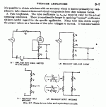
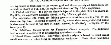
Originally #50 posted by smoking-amp
I looked in my Electronic Designer's Handbook by Landee, Davis and Albrecht and found this for "plate-driven tube" on pages 3-6 and 3-7:
Hello Don,
YEEP, thank you very much, this is excellent!
Can I use this attachment in my blog?
I am sure this will help understanding the coupling triode
(i.e. fourth circuit topology).
Kind regards,
Darius
Hi Darius, "Can I use this attachment in my blog?"
Fine by me, I see the book was published in 1957, so is most likely out of copyright by now. I think Pete Millett's site has some link for checking on copyright status if you want to be certain.
One more thought on a single tube Mu=1 solution:
Lowering the filament voltage of a low Mu tube should decrease the space charge around the cathode, lowering Gm1 more than 1/Rp. So should reduce the Mu. You'll have to lower the operating current to stay within the reduced cathode sourcing ability. This should also improve the linearity of the tube some since "island effect" or "inselbildung" will be reduced as well.
Don
http://members.aol.com/sbench102/dht.html
Mu reduced in flament starved DHT? I would not be too sure about that...
Quoted from link above:
"The "data sheet" values for this tube are rp=10k, gm=0.8mS, mu=8. Reading the values from the above tube curves, near the datasheet operating point, I get rp=8.8k, gm=0.95mS, mu=7.5. Reading the values for the starved filament condition, again near the same operating point, the values are rp=13.5k, gm=0.63mS, mu=8.5. In a real circuit, there is a measureable increase in circuit gain as the filament voltage is lowered, consistent with the tube curves. The big difference, however is still the wide range over which the tube parameters are essentially constant. "
I just noticed the same. Seems the Rp went up more than the gm1 went down. Well, try higher filament voltage then (use a cheap one).
How about putting a stack of donut magnets over the tube (for a cylindically symmetric design) to curve the electron pathes in spirals. No idea what that will do to the Mu.
Don
How about putting a stack of donut magnets over the tube (for a cylindically symmetric design) to curve the electron pathes in spirals. No idea what that will do to the Mu.
Don
Hello Don,
ok, I made a link to this thread so far.
I am going to start a new blog hatetepe://line-pre.blogspot.com/ for the pre.
When it is finished (schematics) I open a new thread for discussion in the preamp.
Kind regards,
Darius
Originally #55 posted by smoking-amp
Hi Darius, "Can I use this attachment in my blog?"
Fine by me, I see the book was published in 1957, so is most likely out of copyright by now. I think Pete Millett's site has some link for checking on copyright status if you want to be certain.
...
Don
ok, I made a link to this thread so far.
I am going to start a new blog hatetepe://line-pre.blogspot.com/ for the pre.
When it is finished (schematics) I open a new thread for discussion in the preamp.
Kind regards,
Darius
Unity µ triode as phase inverter blog
Hello,
I just finished the blog for the phase inverter.
link
I took some photos of the triode section of the ECLL800.
Note the construction of the grid.
Scrolling down, you'll find the schematic for the pre,
this will be moved to the following blog.
CC
Kind regards,
Darius
Hello,
I just finished the blog for the phase inverter.
link
I took some photos of the triode section of the ECLL800.
Note the construction of the grid.
Scrolling down, you'll find the schematic for the pre,
this will be moved to the following blog.
CC
Kind regards,
Darius
Re: Unity µ triode as phase inverter blog
What are the main differences between the "gyrator" stage in your drawing and an ordinary mu-follower?
Jan E
What are the main differences between the "gyrator" stage in your drawing and an ordinary mu-follower?
Jan E
- Status
- This old topic is closed. If you want to reopen this topic, contact a moderator using the "Report Post" button.
- Home
- Amplifiers
- Tubes / Valves
- pse help, unity µ triode as a phase inverter