#10
Hi,
the schematic does not exist at the moment.
When it is finished, I'll make a new thread
about this pre.
@ kenpeter @ Don
I think the attachments from this thread
are interesting for you.
Isn't it possible to upload a 417Kb zip here?
Kind regards,
Darius
Originally #10 posted by kenpeter
Incomplete OT schematic without part values ...
I'm not sure which rail you prefer common to
power noise in this situation. Depends what
are you intending to drive in the next stage?
What was the trouble with Mu>1 and a resistive
divider??
---------------------------------------------------------
Nutz... I inverted twice.... Thats not helpful!
If I make the inverted triode behave as a follower
then overall Mu does not revert to 1 as intended.
I don't see an easy way to fix this.
Hi,
the schematic does not exist at the moment.
When it is finished, I'll make a new thread
about this pre.
@ kenpeter @ Don
I think the attachments from this thread
are interesting for you.
Isn't it possible to upload a 417Kb zip here?
Kind regards,
Darius
#22,21
#22
"I think the attachments from this thread
are interesting for you."
Very interesting. The signal path outlined in red helps a lot
#21
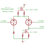
Don, I think I follow and it looks like the same idea. No grid current... Here's my doodle along the same lines. I was thinking similar triodes but the slight mismatch is interesting. Or I may be off in the weeds
Cheers,
Michael
#22
"I think the attachments from this thread
are interesting for you."
Very interesting. The signal path outlined in red helps a lot
#21
Don, I think I follow and it looks like the same idea. No grid current... Here's my doodle along the same lines. I was thinking similar triodes but the slight mismatch is interesting. Or I may be off in the weeds
Cheers,
Michael
Attachments
Take any tube and select load resistance and idle current to get exactly unity gain. No feedback, the problem solved. However, without feedback it will be highly dependable on the tube used, but it is what you need. Tube gurus will be happy with your design creating new fashions and urban legends about different sounds of different tubes.
Wavebourn said:However, without feedback it will be highly dependable on the tube used, but it is what you need. Tube gurus will be happy with your design creating new fashions and urban legends about different sounds of different tubes.
So true! -- I would wire up a unity-gain plate follower and call it a day

"Here's my doodle along the same lines. I was thinking similar triodes but the slight mismatch is interesting." Ken
Looks good to me. Maybe want to upgrade those depletion mode CCS's to cascode ones for lower capacitance effects. Obviously this approach has a close parallel with Darius's fourth topology or triode transformer mode. But two tubes to get unity gain.....? (OK, I know, op. amps have dozens of transistors, and people still use them for unity gain at times.)
"Take any tube and select load resistance and idle current to get exactly unity gain. No feedback, the problem solved. However, without feedback it will be highly dependable on the tube used, but it is what you need. Tube gurus will be happy with your design creating new fashions and urban legends about different sounds of different tubes." Anatoliy
Definitely the obvious solution, but Darius apparently doesn't consider cathode degeneration as no-feedback. (or he would just use the usual split load concertina splitter) Not sure whether Darius would consider a low plate resistor alone to be linear enough. He should add to his "rules" that nothing can be done easily.
"I would wire up a unity-gain plate follower and call it a day" Jon
I'm afraid thats got obvious neg. feedback. (Bad boy. Go to jail!) We have to hide the feedback inside the tube Mu factor some how, unless you can come up with a stealth plate feedback resistor. How about a graphite mounting post (carbon arc rod) for the plate cap lead?
The pentode scheme (g2 driven) still seems the easiest way so far, to me. Or the beam deflector tube scheme. Wonder what Darius will come up with now for his preamp.
Don
How about just coupling the un-inverted signal to the following stage's cathode instead of it's grid. If current gain is required to do that, then put in a cathode follower or Mosfet follower with optional CCS pull-down. So simple, must be something wrong. Uh-Oh, I'll bet cathode followers are against the "rules" too.
Don
Don
The triode has feedback between all three terminals. Even the plate
resistor presents a negative feedback. It is hard to call any triode
circuit (except perhaps the lower triode of a cascode) one without
negative feedback.
Oldeurope will have to define which modes of negative feedback are
acceptable, if we are to understand the rules of his game. So far he
has given us only intrinsic voltage feedback from the plate (resistor)
to work with. I take nothing else for granted.
You could ground that biased and bypassed node
and it would still "work". But then you have to pull
the lower plate negative to shut off grid conduction.
I thought this way of bias might be convenient???
If bias works at all here, and I'm not entirely sure...
Way outside the box, even for me.
and it would still "work". But then you have to pull
the lower plate negative to shut off grid conduction.
I thought this way of bias might be convenient???
If bias works at all here, and I'm not entirely sure...
Way outside the box, even for me.
Same circuit, different drawing... New symbol.
Was giving me a headache trying to wrap my
mind around the abomination I had created.
I needed a different way to draw an inverted
triode. One that would convey the plate as the
control element, and the grid as the anode.
Was giving me a headache trying to wrap my
mind around the abomination I had created.
I needed a different way to draw an inverted
triode. One that would convey the plate as the
control element, and the grid as the anode.
Attachments
Ken, post #29 schematic:
Whoa! Is this thing still conducting normal electrons? OK, looks interesting, attenuate first with inverted triode (neg. plate input, hi Z input, pos. grid output), then amplify with grounded grid. This setup will definitely drive the serviceguy nuts someday. Makes sense to attenuate first with the inverted triode though with its grid output, but it will have trouble getting much current out for the subsequent grounded grid stage cathode. Assuming 1/Mu1 for the 1st stage, I think the 2nd gives Mu2-1 gain (the cathode variation eats 1 Mu from the output)
To address the current disparity, maybe should ground the grid of the 1st tube, but still use negative plate bias for input on it's plate. Then take it's non-inverted cathode signal as the output to the grid of a 2nd conventional grounded cathode stage. Then there's no loading on the weak 1st stage. The second stage provides normal Mu gain and inversion. 1st stage giving 1/Mu+1 and 2nd stage giving Mu gain.
"Oldeurope will have to define which modes of negative feedback are acceptable, if we are to understand the rules of his game."
Yes, we do need some clarification on just what the rules are here. But it's interesting to press the confines of the envelope for tube circuit design in any case. Really weird circuitry as SY noticed.
late edit to post #26:
I attributed the 1st quote there to Ken, but it should be to Michael Koster who had popped in. Sorry for the mixup.
Don
Attachments
Huh, ya know, it looks like that last circuit would work just fine with conventional B+ on the V1 plate input too. With a CCS in the cathode, the plate Z goes way up, even in conventional (plate as plate) mode. So that Rb1 resistor could be a high value going to B+ instead of -Vb.
Don
Don
The post #33 schematic gave me an idea for improving the screen driven pentode scheme. With constant current thru the tube, the screen current should be near constant, so the screen should have relatively high input Z. Total gain would be approx. 1/Mu_screen times Mu_plate. Since this will be a bit more than unity, the cathode resistor Rk can be used to degenrate gain a little further till unity gain is reached.
Don
Don
Attachments
smoking-amp said:
"Take any tube and select load resistance and idle current to get exactly unity gain. No feedback, the problem solved. However, without feedback it will be highly dependable on the tube used, but it is what you need. Tube gurus will be happy with your design creating new fashions and urban legends about different sounds of different tubes." Anatoliy
Definitely the obvious solution, but Darius apparently doesn't consider cathode degeneration as no-feedback. (or he would just use the usual split load concertina splitter) Not sure whether Darius would consider a low plate resistor alone to be linear enough. He should add to his "rules" that nothing can be done easily.
What cathode degeneration?
I proposed a single solution with no feedback added.
kenpeter said:The triode has feedback between all three terminals. Even the plate
resistor presents a negative feedback. It is hard to call any triode
circuit (except perhaps the lower triode of a cascode) one without
negative feedback.
It is true, but such a feedback is unavoidable (like feedbacks through inter-electrode capacitances)
or... what if to hide a transformer inside of a glass bulb?

Oops, my last post #36 schematic is NON-inverting, darn. A clever piece of wire. Nice complementary current mirror anyway.
"What cathode degeneration?" Anatoliy
True indeed, but with just a low value plate load resistor to kill the gain down to unity, the tube will be running almost in pentode mode with high distortion. Some cathode degeneration could fix that.
Don
"What cathode degeneration?" Anatoliy
True indeed, but with just a low value plate load resistor to kill the gain down to unity, the tube will be running almost in pentode mode with high distortion. Some cathode degeneration could fix that.
Don
#29 #32
Hi kenpeter,
I tested the arrangement in post #32.
There are two mayor problems.
- First the gain of the inverted tube µ'< 1/µ .
See post #12.
- Second, the inverted mode triode needs a special construction
to get low distortion and a reliable value of µ'.
Kind regards,
Darius
Hi kenpeter,
I tested the arrangement in post #32.
There are two mayor problems.
- First the gain of the inverted tube
µ'< 1/µ .See post #12.
- Second, the inverted mode triode needs a special construction
to get low distortion and a reliable value of µ'.
Kind regards,
Darius
- Status
- This old topic is closed. If you want to reopen this topic, contact a moderator using the "Report Post" button.
- Home
- Amplifiers
- Tubes / Valves
- pse help, unity µ triode as a phase inverter