oshifis said:That is almost everything we need... Well I nearly forgot sonic quality...
Exactly. As the references and regulators get more ideal and quieter, the sonic quality does indeed improve, assuming the goal of the electronics is to alter the signal as little as possible except for magnitude.
SY said:assuming the goal of the electronics is to alter the signal as little as possible except for magnitude.
That's one good way of looking at it. Another is to say that the system goal is to create an effective and enjoyable illusion of the performance. Another is to have fun, and so it goes. Each recipe has room for a little expression.
Sheldon

Re: #23
You can do that.
There are lots of things you don't "need". As for myself, I use whatever technology gets the job done. Solid state CCSs simply work better than the hollow state version. The gain, and hence the impedance, is higher, and the high frequency performance better, and lets the hollow state do its job better.
The MOSFET source follower is sonically benign, and has way more current sourcing capability, and a much lower Zo than any hollow state driver. This is a great help with slapping around the control grids of 845s and Class A2 RF triodes, or other types like the 814 or 1624 that can only operate at tinywatts in any Class *1 mode. Here's an exerpt from the 1624 spec sheet:
Now, ideal drivers and ideal PSs are unrealistic. However, nothing will get you closer to a zero impedance driver than a source follower. Were I to use this one, or Class AB2 807s for lotsawatts, you betcha I'll use solid state. And if power MOSFETs were around in the 1930s, so would have O. H. Schade.
oshifis said:Is it possible to use a pentode CCS in the LTP cathodes (in order to get rid off silicon in the signal path)?
You can do that.
oldeurope said:You don't need semiconductors in a tube amp.
I don't understand why people use semiconductors in tube amps
and why they treat tubes like semiconductors.
Kind regards
Darius
There are lots of things you don't "need". As for myself, I use whatever technology gets the job done. Solid state CCSs simply work better than the hollow state version. The gain, and hence the impedance, is higher, and the high frequency performance better, and lets the hollow state do its job better.
The MOSFET source follower is sonically benign, and has way more current sourcing capability, and a much lower Zo than any hollow state driver. This is a great help with slapping around the control grids of 845s and Class A2 RF triodes, or other types like the 814 or 1624 that can only operate at tinywatts in any Class *1 mode. Here's an exerpt from the 1624 spec sheet:
With zero-impedance driver, and perfect regulation, plate-circuit distortion does not exceed 2.0%
Now, ideal drivers and ideal PSs are unrealistic. However, nothing will get you closer to a zero impedance driver than a source follower. Were I to use this one, or Class AB2 807s for lotsawatts, you betcha I'll use solid state. And if power MOSFETs were around in the 1930s, so would have O. H. Schade.
Well I finally built this.
Very transperant detailed in sound compared the the SRPP. THD dropped from 0.22% to 0.03%.
However, I have to lower the input by 50% or the cathode follower clips. It works out to anything over 2V p-p (from the gain stage) into the cathode follower clips. This is only 2/33=0.06 V p-p input to th entire stage.
rdf said:Would it need a neg supply? With the op points shown that circuit should swing an order of magnitude more voltage in its sleep.
My mistake; I was thinking about my CF circuit. Or any other where the grid is near DC ground. The actual circuit has plenty of swing capability.
I think a voltage map is in order. Something is miswired or broken.
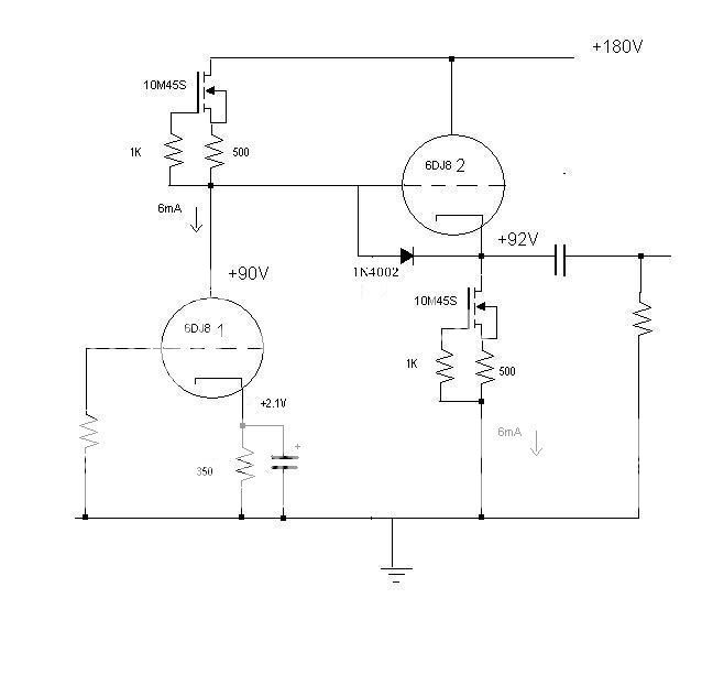
Is the protection diode really a 4002? That's flirting with danger; a 4007 would be better. But yes, you ought to be able to swing at least 20 volts out of this. What's the voltage across the 500R on the CF?
And a dumb question: do you have a probe that you think is 1x accidentally set to 10x? (I've made THAT mistake more times than I care to remember)
And a dumb question: do you have a probe that you think is 1x accidentally set to 10x? (I've made THAT mistake more times than I care to remember)
I think I have two issues:
1. The inpput of my soundcard is actually clipping, not the CF.
2. The improvement I hear in sound quality by turning down the digital feed to the DAC is effectively lowering the I/V resistor. This DAC recommends less than 0.025V on its output and that just happens to be where the sound smooths out. Never noticed before because the SRPP's distortion masked the DAC's distortion. This new stage is so transperant it is amazing. Time for me to look at a better I/V scheme.
- Status
- This old topic is closed. If you want to reopen this topic, contact a moderator using the "Report Post" button.
- Home
- Amplifiers
- Tubes / Valves
- TubeCad Journal FET CCS