BJT / MOSFET in cathode circuit?
Greetings All,
Anyone using a BJT or MOSFET transistor - as amplifier - in the cathodes of a diff. pair with CCS?
I do not have the possibility to build prototypes at the moment, so I have simulated the circuit described above. It is wisely used by Allen Wright of Vacuum State. See schematics of RTP3 pre-amp on his site.
The JFET is ok for small amplitude. BJT (2N3904 or BC549) and MOSFET (IRFP240) are looking good with a 6922/6DJ8 for a 6L6/KT66 driver. On simulation, I obtain 70Vpk-pk or more with 6N1P. The CCS sinks 18-20mA (9-10mA per triode).
I should be able to build a prototype this coming (European) Winter.

Cheers.
Serge
Greetings All,
Anyone using a BJT or MOSFET transistor - as amplifier - in the cathodes of a diff. pair with CCS?
I do not have the possibility to build prototypes at the moment, so I have simulated the circuit described above. It is wisely used by Allen Wright of Vacuum State. See schematics of RTP3 pre-amp on his site.
The JFET is ok for small amplitude. BJT (2N3904 or BC549) and MOSFET (IRFP240) are looking good with a 6922/6DJ8 for a 6L6/KT66 driver. On simulation, I obtain 70Vpk-pk or more with 6N1P. The CCS sinks 18-20mA (9-10mA per triode).
I should be able to build a prototype this coming (European) Winter.
Cheers.
Serge
#23
Yes, of course.
You don't need semiconductors in a tube amp.
I don't understand why people use semiconductors in tube amps
and why they treat tubes like semiconductors.
Kind regards
Darius
Originally #23 posted by oshifis
Is it possible to use a pentode CCS in the LTP cathodes (in order to get rid off silicon ... )?
Yes, of course.
You don't need semiconductors in a tube amp.
I don't understand why people use semiconductors in tube amps
and why they treat tubes like semiconductors.
Kind regards
Darius
I don't understand why people use semiconductors in tube amps
Because for maintaining a constant voltage or a constant current, their performance is superior. This allows the tubes which handle the signal to operate more ideally.
Tubes compound CCS
Hello !
The link to TubeCAd Journal about CCS in a compound line preamp...
http://www.tubecad.com/february2000/page14.html
R.C.
Hello !
The link to TubeCAd Journal about CCS in a compound line preamp...
http://www.tubecad.com/february2000/page14.html
R.C.
Led's are like other diodes. The variation in forward voltage is small. So they are easy to predict.
If the voltage changes on plate 1, it must change on the grid of tube 2. However, the cathode voltage for tube 2 will simply follow its grid voltage - hence the name cathode follower.
Sheldon
If the voltage changes on plate 1, it must change on the grid of tube 2. However, the cathode voltage for tube 2 will simply follow its grid voltage - hence the name cathode follower.
Sheldon
Hi regal,
Please think about what I said in post #10.
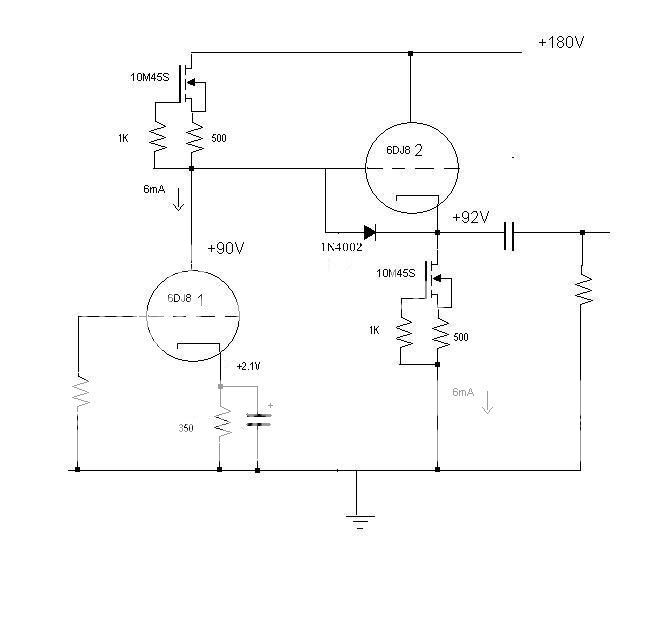
You can pick an LED for the bias and it will provide a fixed bias depending on the physics of the device. Now, adjust the current through the CCS to cause the plate voltage to be 90V, or whatever you want. The current will be whatever it needs to be to allow the plate voltage to be what you have chosen at the bias that you have chosen.
Now having said that, I would recommend that you experiment with the circuit. You will find a sweet spot (or maybe a couple) at different variations of plate current and plate voltage. Use a nice wire-wound pot in the cathode to set the bias and a trim pot in parallel with the CCS Rset to set the current. Once you have found the operating point that you like, replace the pots with fixed resistors. You might also want to experiment with an LED in the cathode.
Don’t worry about exceeding the 90V by a few volts, and you might consider referencing the heater with a positive voltage.
Dave
Please think about what I said in post #10.
You can pick an LED for the bias and it will provide a fixed bias depending on the physics of the device. Now, adjust the current through the CCS to cause the plate voltage to be 90V, or whatever you want. The current will be whatever it needs to be to allow the plate voltage to be what you have chosen at the bias that you have chosen.
Now having said that, I would recommend that you experiment with the circuit. You will find a sweet spot (or maybe a couple) at different variations of plate current and plate voltage. Use a nice wire-wound pot in the cathode to set the bias and a trim pot in parallel with the CCS Rset to set the current. Once you have found the operating point that you like, replace the pots with fixed resistors. You might also want to experiment with an LED in the cathode.
Don’t worry about exceeding the 90V by a few volts, and you might consider referencing the heater with a positive voltage.
Dave
Re: #23
No, they are not needed. I use them in some places, mostly out of laziness. They don't take up much space and they don't need a heater. I've used them for current sources, and sometimes in power supplies. I can stuff them into a chassis that is already crammed full.
I have no problem with the purist approach - in fact, I think it cool that some of us go that way. But audio is a fun hobby for me, and mixing up different technologies is part of the fun. Now, surfing is a passion, and for that I'm a purist. No mechanical aids, ala towing into waves. If I can't paddle into it, I don't go.
Sheldon
oldeurope said:You don't need semiconductors in a tube amp.
I don't understand why people use semiconductors in tube amps
and why they treat tubes like semiconductors.
No, they are not needed. I use them in some places, mostly out of laziness. They don't take up much space and they don't need a heater. I've used them for current sources, and sometimes in power supplies. I can stuff them into a chassis that is already crammed full.
I have no problem with the purist approach - in fact, I think it cool that some of us go that way. But audio is a fun hobby for me, and mixing up different technologies is part of the fun. Now, surfing is a passion, and for that I'm a purist. No mechanical aids, ala towing into waves. If I can't paddle into it, I don't go.
Sheldon
David Davenport said:
Don’t worry about exceeding the 90V by a few volts, and you might consider referencing the heater with a positive voltage.
Dave
The U+k/f- is 120V max, so I am thinking the heater is safe. This DAC is on a PCB so referencing the heater would be difficult
Originally #26 posted by SY
Because for maintaining a constant voltage or a constant current, their performance is superior. This allows the tubes which handle the signal to operate more ideally.
Hi SY
It is possible to get excellent results from semiconductors and tubes.
My hobby is tubes. For maintaining a constant voltage or a constant current,
tubes performance is superior, too.
These days tubes are available again new produced and in big quantity's.
Thus I use them.
Kind regards
Darius
Yes, and they were also inaccurate and drifted with tube ageing.Rectifications and regulations without solid state devices were costly, heavy, big, more energy hungry, required maintenance.
People did the best they could in the time before today's SS devices became available, and all credit to them. However, I bet the designers of yesteryear would have jumped at the chance to use today's superior and much less costly SS devices.
Other than lower output impedance, lower drift, lower noise, better stability, better load and line rejection, lower heat, and smaller size, there's no real advantage to using solid state for voltage regulation or references.
And other than higher source impedance, lower noise, higher compliance, lower parts count, less heat, and no heater-cathode voltage issues, there's no real advantage to using solid state for current regulation or references, either.
And other than higher source impedance, lower noise, higher compliance, lower parts count, less heat, and no heater-cathode voltage issues, there's no real advantage to using solid state for current regulation or references, either.
- Status
- This old topic is closed. If you want to reopen this topic, contact a moderator using the "Report Post" button.
- Home
- Amplifiers
- Tubes / Valves
- TubeCad Journal FET CCS