#39
Hi SY,
I agree, thanks.")
Please find a name for this factor.
This factor tells you e.g. if a cathode bypass makes sense or not.
Since I don't like an (electrolytic) bypass cap and its “ESR” influence
this factor is a good tool in triode circuit design.
There are lots of additional aspects the factor helps for.
Kind regards,
Darius
Originally #39 posted by SY
"Factor" appears to be the ratio between the load impedance as seen by the tube's plate, and the total effective internal resistance of the tube (which includes the degenerative term).
...
Hi SY,
I agree, thanks.
Please find a name for this factor.
This factor tells you e.g. if a cathode bypass makes sense or not.
Since I don't like an (electrolytic) bypass cap and its “ESR” influence
this factor is a good tool in triode circuit design.
There are lots of additional aspects the factor helps for.
Kind regards,
Darius
I think this is not far from optimum (with my present components)with a 6SN7 and 801A. The factor is about 5. It's on the margin for a 2VRMS input, but would work fine with my source.
I ordered some wire for the transformers. Now have to rig up an old sewing machine for winding.
Sheldon
I ordered some wire for the transformers. Now have to rig up an old sewing machine for winding.
Sheldon
Attachments
Sheldon said:I think this is not far from optimum (with my present components)with a 6SN7 and 801A. The factor is about 5. It's on the margin for a 2VRMS input, but would work fine with my source.
I ordered some wire for the transformers. Now have to rig up an old sewing machine for winding.
Sheldon
Sheldon,
What's the voltage rating of the 2.2uF cap?
TIA,
-- josé k.
korneluk said:What's the voltage rating of the 2.2uF cap?
It's at the cathode potential of the 801, so about 130V. I would use something rated at least 200V.
Sheldon
Sheldon said:
It's at the cathode potential of the 801, so about 130V. I would use something rated at least 200V.
Sheldon
Could you replace the 5.4K reistor by a 25mA tube current source - as long as it does not have any caps that act as a cathode bypass, of course?
TIA,
-- josé k.
korneluk said:Could you replace the 5.4K reistor by a 25mA tube current source - as long as it does not have any caps that act as a cathode bypass, of course?
Sure, by what does it add in this topology? I (admitting my inexperience) don't see why a high impedance at that point is of much value. It only sets the DC operating point. Remember, this circuit is already compensated for imperfections in the power supply response. I think the circuit, for good stereo imaging, is probably best with relatively well balanced output tubes either way - ccs or resistor. That's not hard to do, and a lot less complicated than adding a current sink.
Sheldon
Chb voltage rating
Hi Sheldon
 Pull the 6SN7 and measure the voltage drop at the cathode resistor of the output triode.
This is the minimum voltage rating for Chb.
Make sure that the resistor is able to handle the power dissipation.
Kind regards,
Darius
Originally #46 posted by Sheldon
It's at the cathode potential of the 801, so about 130V. I would use something rated at least 200V.
Sheldon
Hi Sheldon
Pull the 6SN7 and measure the voltage drop at the cathode resistor of the output triode.This is the minimum voltage rating for Chb.
Make sure that the resistor is able to handle the power dissipation.
Kind regards,
Darius
Re: Transformer #44
 The commercial output transformer manufacturers will kill him, hi hi.
Kind regards,
Darius
Sheldon said:Credit to Yves
The commercial output transformer manufacturers will kill him, hi hi. Kind regards,
Darius
Re: #39
Hi, excuse me for butting in, but if the factor is, as it looks to be, the ratio of load impedance to effective source impedance, then would the term "Damping Factor" be appropriate?
Cheers,
Michael
oldeurope said:
Hi SY,
I agree, thanks.
Please find a name for this factor.
This factor tells you e.g. if a cathode bypass makes sense or not.
Since I don't like an (electrolytic) bypass cap and its “ESR” influence
this factor is a good tool in triode circuit design.
There are lots of additional aspects the factor helps for.
Kind regards,
Darius
Hi, excuse me for butting in, but if the factor is, as it looks to be, the ratio of load impedance to effective source impedance, then would the term "Damping Factor" be appropriate?
Cheers,
Michael
Re: Re: Transformer #44
Thanks Darius
Ah, right. I could do that safely with the resistors I have for the project (5x5W 27k in parallel), but I see your point. C2 needs to be rated nearly the full B+ for full protection (or, the compensation resistors become fuses).
Might not be worth the effort to hire the hit men. Not that many looney DIY'rs willing to wind up transformers. Plus, it's a pain getting laminations and the other components. Anyone need some EI84 lams and bobbins- I've got plenty of extra? I don't really do this to save money, just for fun.
Sheldon
Thanks Darius
oldeurope said:
This is the minimum voltage rating for Chb.
Make sure that the resistor is able to handle the power dissipation.
Ah, right. I could do that safely with the resistors I have for the project (5x5W 27k in parallel), but I see your point. C2 needs to be rated nearly the full B+ for full protection (or, the compensation resistors become fuses).
oldeurope said:The commercial output transformer manufacturers will kill him, hi hi.
Might not be worth the effort to hire the hit men. Not that many looney DIY'rs willing to wind up transformers. Plus, it's a pain getting laminations and the other components. Anyone need some EI84 lams and bobbins- I've got plenty of extra? I don't really do this to save money, just for fun.
Sheldon
SY said:Sure, but the problem is connotation. When someone in home audio hears the words "damping factor," 8 ohms is reflexively assumed, as is a reactive load (i.e., the existence of something that needs to be damped).
Oh, I see what you're saying. I just assume that Damping Factor means impedance ratio from a circuit design perspective. The origin of the term probably has to do with reactive loads so it may not be the best term for this use.
I have seen the term "Drive Factor" but that may be too ambiguous.
Michael
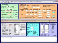
triode self linearize factor
Hello,
please read this text :
This important aspect is covered by the formula, too.
It is a "self linearize" factor for a triode stage.
Kind regards,
Darius
Hello,
please read this text :
http://coupling-triode.blogspot.com/
Grounded cathode and grounded grid circuit: The triode works here without mutal conductance slope distortions if ... By this methode the triode can be operated linearly without applying negative feedback and this is the way that I have designed the RIAA 2007.
This important aspect is covered by the formula, too.
It is a "self linearize" factor for a triode stage.
Kind regards,
Darius
Attachments

#56
Hm, the question is do you need the compensation (Chb)?
I need it because I am using a triode.
Loftin White needs it because g2 is connected to a tapping of the cathode resistor.
Why do you need it?
I know this thread is against the technical forum rules.
But you try to replace tubes by mosfets, this makes the moderators
happy.
BTW: I think the Triodelington is the better triode replacement.
Please note that the use of BJTs is not against the forum rules.
Kind regards,
Darius
IGBT " Mu Starver" may provide a near linear gain for
Mu, but the Vacuum Diode transfer function gives us
Triode law X^1.5 "Plate Resistance". Last I read, the
Vacuum Diode was still considered a Tube? My symbol
for Vacuum Diode may not have been legible as such.
There was none in LT-Spice, I drew the best I could.
This stage with the real plate is the only gain stage.
My depletion MOSFET in the input stage? OK, you got
me there. No tube, but it was only intended to have a
unity gain with low impedance, once all resistors have
been scaled accordingly. Call it an inverting follower...
Unity gain followers are nothing new in this thread.
Without this very low (or at least very stable) driving
impedance, the Mu Starver in the next stage may not
be as accurate.
CHB you say is not relevant due to the MOSFET? But
my circuit has full anode feedback, should respond to
power supply noise at the anode, just as-if a Triode.
Not the high impedance PSRR of the usual FET Drain.
Same theory of operation as O.H. Schade (RCA 1938)
6L6 (Screen not strapped to Plate) Triode emulation.
With a PSRR no better than an emulated triode with
Mu=1, CHB seems very relevant here. Have I missed
something?
Your Triodelington does indeed look interesting, and
might be the simpler circuit. For one or both stages...
But relies perhaps too much on the thermal stability
of Beta... Any local feedback to stabilize the Beta also
messes with the behavior of the Triode... IGBT might
be more stable and linear substitute than BJT here.
Might still need to rely on an unbypassed cathode
resistor to sample a voltage for the gate.
Not yet sure how I would take feedback from the OPT
to linearize my iron with the Triodelington?
- Status
- This old topic is closed. If you want to reopen this topic, contact a moderator using the "Report Post" button.
- Home
- Amplifiers
- Tubes / Valves
- Darius Loftin White explained