And the Power Supply
This conversion re-uses most of the components from the initial version, amp and power supply. The one exception is that I will need to wind some transformers to for regular SE duty. I can use the same chassis too. If I had to change that, I might not do it.
Sheldon
This conversion re-uses most of the components from the initial version, amp and power supply. The one exception is that I will need to wind some transformers to for regular SE duty. I can use the same chassis too. If I had to change that, I might not do it.
Sheldon
Attachments
RE: Version1 (With Bootstrap)
Current set by 625R source of lower LND150 = 1ma???
If so, then 1ma thru 10R at that drain is a 0.01V drop.
Never changing, never doing anything too interesting.
Even the bootstrap end tied here won't conduct any
variance thru the lower 10R due to the CCS.
Quite probably the other 10R above the top LND150
is equally inert. It might see some slight activity due
to the bootstrap capacitor... I am not sure it has any
other significant effect. Is it necessary?
I often throw in overzealous optional parts, and later
remove them... I had one thing in mind when I drew
them there, but then a crazy new idea evolves.
kenpeter said:RE: Version1 (With Bootstrap)
Current set by 625R source of lower LND150 = 1ma???
If so, then 1ma thru 10R at that drain is a 0.01V drop.
Never changing, never doing anything too interesting.
Even the bootstrap end tied here won't conduct any
variance thru the lower 10R due to the CCS.
Quite probably the other 10R above the top LND150
is equally inert. It might see some slight activity due
to the bootstrap capacitor... I am not sure it has any
other significant effect. Is it necessary?
I often throw in overzealous optional parts, and later
remove them... I had one thing in mind when I drew
them there, but then a crazy new idea evolves.
I copied that from a different version that uses DN2540 at higher currents. Just left the drain "stoppers" in. They were originally suggested by someone here, as I was having some issues that could have been oscillation related. They may well do nothing.
Sheldon
Sheldon
#21
Hello Sheldon,
Yes, this is the way I like it.")
And I like the tubes you are going to use.
I think you'll have something between 90VDC to 100VDC at the cathode?
Did you calculate the expected output resistance of the driver and it's
"characteristic factor"?
Kind regards,
Darius
Hello Sheldon,
Sheldon said:Or one I suspect you will prefer:
Yes, this is the way I like it.
And I like the tubes you are going to use.
I think you'll have something between 90VDC to 100VDC at the cathode?
Did you calculate the expected output resistance of the driver and it's
"characteristic factor"?
Kind regards,
Darius
Re: #21
I didn't have to guess at your preference.
With these values, the voltage at the output tube cathode will be about 135V, at a little under 30mA. With a bias offset of -26V, the grid will be at about 110V.
Using 60k for the ra, and a u of 70, I get about 90k for the output impedance. With an estimated 50pF input capacitance for the 801, that gives me a roll off at about 35kHz - maybe borderline. I like your bootstrap approach with tubes, but I want to avoid having to redo my chassis http://www.diyaudio.com/forums/showthread.php?postid=883561#post883561. I've made a number of changes to the power supply of that amp, so that thread is not the current version, but the rest is the same. I might consider redoing the top plate, as a last resort. That's why I posted the bootstrapped fet follower. I could also simply use the follower after the SL7 without the bootstrap.
I'm not sure about the "characteristic factor". I have seen reference to it on on your blogs, so I'll have to find it and see if I can understand it.
Sheldon
oldeurope said:Yes, this is the way I like it.
And I like the tubes you are going to use.
I think you'll have something between 90VDC to 100VDC at the cathode?
Did you calculate the expected output resistance of the driver and it's
"characteristic factor"?
I didn't have to guess at your preference.
With these values, the voltage at the output tube cathode will be about 135V, at a little under 30mA. With a bias offset of -26V, the grid will be at about 110V.
Using 60k for the ra, and a u of 70, I get about 90k for the output impedance. With an estimated 50pF input capacitance for the 801, that gives me a roll off at about 35kHz - maybe borderline. I like your bootstrap approach with tubes, but I want to avoid having to redo my chassis http://www.diyaudio.com/forums/showthread.php?postid=883561#post883561. I've made a number of changes to the power supply of that amp, so that thread is not the current version, but the rest is the same. I might consider redoing the top plate, as a last resort. That's why I posted the bootstrapped fet follower. I could also simply use the follower after the SL7 without the bootstrap.
I'm not sure about the "characteristic factor". I have seen reference to it on on your blogs, so I'll have to find it and see if I can understand it.
Sheldon
#26
Thanks for your reply.
Hi Sheldon,
I'd like to see ≈95VDC ≈20mA in your application.
Yes, I agree.
At this current µ will be lower and maybe you can take
a lower cathode resistor?
If not you can increase the cathode resistor of the output triode
to get 20mA.
What is the roll off of the output transformer?
The amp looks good..
This is important to understand for a good triode circuit design.
Kind regards,
Darius
Thanks for your reply.
Sheldon said:
I didn't have to guess at your preference.
With these values, the voltage at the output tube cathode will be about 135V, at a little under 30mA. With a bias offset of -26V, the grid will be at about 110V.
...
Sheldon
Hi Sheldon,
I'd like to see ≈95VDC ≈20mA in your application.
Sheldon said:
Using 60k for the ra, and a u of 70, I get about 90k for the output impedance. With an estimated 50pF input capacitance for the 801, that gives me a roll off at about 35kHz - maybe borderline. I like your bootstrap approach with tubes, but I want to avoid having to redo my chassis http://www.diyaudio.com/forums/showthread.php?postid=883561#post883561.
Sheldon
Yes, I agree.
At this current µ will be lower and maybe you can take
a lower cathode resistor?
If not you can increase the cathode resistor of the output triode
to get 20mA.
What is the roll off of the output transformer?
The amp looks good.
.Sheldon said:
I'm not sure about the "characteristic factor". I have seen reference to it on on your blogs, so I'll have to find it and see if I can understand it.
Sheldon
This is important to understand for a good triode circuit design.
Kind regards,
Darius
Re: #26
Thanks Darius,
Do you mean 95V at the cathode or at the grid? At 95V on the grid, the operating point for the driver becomes harder.
I can increase the current in the driver a bit and that will lower the plate and cathode resistors some.
Haven't got an OPT yet. Might use this program to design one: http://www.dissident-audio.com/OPT_da/Page.html
Sheldon
Thanks Darius,
oldeurope said:I'd like to see about 95VDC & about 20mA in your application.
Do you mean 95V at the cathode or at the grid? At 95V on the grid, the operating point for the driver becomes harder.
oldeurope said:.At this current µ will be lower and maybe you can take
a lower cathode resistor?
If not you can increase the cathode resistor of the output triode
to get 20mA.
What is the roll off of the output transformer?
The amp looks good.
I can increase the current in the driver a bit and that will lower the plate and cathode resistors some.
Haven't got an OPT yet. Might use this program to design one: http://www.dissident-audio.com/OPT_da/Page.html
Sheldon
#29
Hello Sheldon,
cathode of course.
Yes you are right. I think it is better to increase the cathode resistor of the output
triode from 4K7Ω to 6K8Ω.
The best is to measure the best value with the oscilloscope.
Kind regards,
Darius
Sheldon said:Thanks Darius,
Do you mean 95V at the cathode or at the grid? At 95V on the grid, the operating point for the driver becomes harder.
Sheldon
Hello Sheldon,
cathode of course.
Yes you are right. I think it is better to increase the cathode resistor of the output
triode from 4K7Ω to 6K8Ω.
The best is to measure the best value with the oscilloscope.
Kind regards,
Darius
#27 "triode design factor" ...
Hi Sheldon,
from your schematic and the following post:
Ra = 420KΩ
Rk = 800Ω
µ = 70
ri = 60KΩ
factor = Ra/(µRk+ri)= 420KΩ / ( 70 x 800Ω + 60KΩ )
= 3,6
You should get 4 or more in a good triode circuit design.
Thus there is something to do.
I am sure increasing Ra to 470KΩ will help.
Kind regards,
Darius
Originally #27 posted by Sheldon
For the characteristic factor I calculate: 420000/(((800)+(1/0.0014))*70) = 0.01.
That's with transconductance expressed as Mhos.
Don't know what it means yet, though.
Sheldon
Hi Sheldon,
from your schematic and the following post:
Originally #26 posted by Sheldon
... Using 60k for the ra, and a u of 70, ... Sheldon
Ra = 420KΩ
Rk = 800Ω
µ = 70
ri = 60KΩ
factor = Ra/(µRk+ri)= 420KΩ / ( 70 x 800Ω + 60KΩ )
= 3,6
You should get 4 or more in a good triode circuit design.
Thus there is something to do.
I am sure increasing Ra to 470KΩ will help.
Kind regards,
Darius
Re: #27 "triode design factor" ...
Thanks Darius. I see where I made the calculation mistake. I'll play with some values a bit. I can use TubeCad1 from John Broskie. Makes it easy to plug in new numbers for the tubes that are listed.
For the SL7, something like 440k, 1mA, and Rk 665 give a value of 4.1. Or 400k, 1.1mA, 560, for 4.0. Can't get much above that with this tube.
With an SN7 at 400k, 1.1mA, 3.6k, 15k Rp, I get about 4.6. At 184k, 2.4mA, 1.3k, 11.5k, I get 4.9. That seems to be about the maximum for reasonable values. Anywhere around 2 -2.5mA seems good. I don't really lose much gain there with the unbypassed cathode either, so I might be able to use it that way. I guess I could also add the bootstrap/follower, FET or tube. Any reason I couldn't use a 9pin tube for that duty - something like a 12BH7 that would take the voltage? Adding it would not be too much work on the chassis, but I'd need to stuff another filament transformer in there.
Sheldon
oldeurope said:
Ra = 420KΩ
Rk = 800Ω
µ = 70
ri = 60KΩ
factor = Ra/(µRk+ri)= 420KΩ / ( 70 x 800Ω + 60KΩ )
= 3,6
You should get 4 or more in a good triode circuit design.
Thus there is something to do.
I am sure increasing Ra to 470KΩ will help.
Thanks Darius. I see where I made the calculation mistake. I'll play with some values a bit. I can use TubeCad1 from John Broskie. Makes it easy to plug in new numbers for the tubes that are listed.
For the SL7, something like 440k, 1mA, and Rk 665 give a value of 4.1. Or 400k, 1.1mA, 560, for 4.0. Can't get much above that with this tube.
With an SN7 at 400k, 1.1mA, 3.6k, 15k Rp, I get about 4.6. At 184k, 2.4mA, 1.3k, 11.5k, I get 4.9. That seems to be about the maximum for reasonable values. Anywhere around 2 -2.5mA seems good. I don't really lose much gain there with the unbypassed cathode either, so I might be able to use it that way. I guess I could also add the bootstrap/follower, FET or tube. Any reason I couldn't use a 9pin tube for that duty - something like a 12BH7 that would take the voltage? Adding it would not be too much work on the chassis, but I'd need to stuff another filament transformer in there.
Sheldon
Darius,
What is your opinion about this amp?
http://www.ispra.net/audio/DCSingleEndedAmplifier/index.php
Danke,
-- josé k.
What is your opinion about this amp?
http://www.ispra.net/audio/DCSingleEndedAmplifier/index.php
Danke,
-- josé k.
no Loftin White
Hello josé k.
Please have a look at post #17.
Please note the cathode decoupling cap C5.
This is forbidden in Loftin White because C3 and C5
are opening the closed output current loop.
Quote from Radio News Feb.1930: "A condenser, C2,
of about 1 microfarad is needed to form a local signal
circuit in the output circuit including association of any
suitable loud speaker as indicated."
link
I don't like C6. I a good triode design it isn't necessary.
I made a formula for you that gives you a factor.
If this factor is four or more, you don't need C6.
For me it is important to eliminate coupling caps and cathode
resistor bypass caps, no semiconductors please.
Kind regards,
Darius
Originally #35 posted by korneluk
Darius,
What is your opinion about this amp?
http://www.ispra.net/audio/DCSingleEndedAmplifier/index.php
http://www.ispra.net/audio/DCSingleEndedAmplifier/2A3DC/schematics.gif
Danke,
-- josé k.
Hello josé k.
Please have a look at post #17.
Please note the cathode decoupling cap C5.
This is forbidden in Loftin White because C3 and C5
are opening the closed output current loop.
Quote from Radio News Feb.1930: "A condenser, C2,
of about 1 microfarad is needed to form a local signal
circuit in the output circuit including association of any
suitable loud speaker as indicated."
link
I don't like C6. I a good triode design it isn't necessary.
I made a formula for you that gives you a factor.
If this factor is four or more, you don't need C6.
For me it is important to eliminate coupling caps and cathode
resistor bypass caps, no semiconductors please.
Kind regards,
Darius
#34
Hello Sheldon,
You'll need up to 80Vpp at the output triode.
A 6SN7 has a µ of 20 thus you'll need 4Vpp at the input.
Too much to drive the amp from line level (2Vpp).
The amp should be full driven between 1Vpp to 2Vpp.
If 4Vpp isn't to much for you, take the 6SN7. It is easy to get
a high factor and low output impedance from this tube.
The 12BH7 has a µ of 17.
Please note that the operating voltage Uak will be below 100V
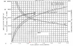
6SL7:
See attached graph @Uak = 100VDC and Ia = 900µA:
Ra = 470KΩ
Rk = 820Ω
µ = 70
ri = 57KΩ
factor = Ra/(µRk+ri)= 470KΩ / ( 70 x 820Ω + 57KΩ )
= 4,1
Please note that the Loftin White topology makes this possible.
In an conventional circuit you have to calculate the AC load
caused by the grid biasing resistor parallel to Ra.
Uak [DC level between anode and cathode]
Rk [cathode resistor]
ri [AC resistance, differential resistance of the triode between anode and cathode]
Upp [peak to peak Voltage]
µ [no load operation amplification factor]
Kind regards,
Darius
Hello Sheldon,
You'll need up to 80Vpp at the output triode.
A 6SN7 has a µ of 20 thus you'll need 4Vpp at the input.
Too much to drive the amp from line level (2Vpp).
The amp should be full driven between 1Vpp to 2Vpp.
If 4Vpp isn't to much for you, take the 6SN7. It is easy to get
a high factor and low output impedance from this tube.
The 12BH7 has a µ of 17.
Please note that the operating voltage Uak will be below 100V
6SL7:
See attached graph @Uak = 100VDC and Ia = 900µA:
Ra = 470KΩ
Rk = 820Ω
µ = 70
ri = 57KΩ
factor = Ra/(µRk+ri)= 470KΩ / ( 70 x 820Ω + 57KΩ )
= 4,1
Please note that the Loftin White topology makes this possible.
In an conventional circuit you have to calculate the AC load
caused by the grid biasing resistor parallel to Ra.
Uak [DC level between anode and cathode]
Rk [cathode resistor]
ri [AC resistance, differential resistance of the triode between anode and cathode]
Upp [peak to peak Voltage]
µ [no load operation amplification factor]
Kind regards,
Darius
Attachments
Re: #34
Thank you for your reply Darius,
The bias on the 801 would be around -30V, so I was assuming about 60vpp. That's still marginal with a standard line level, but my preamp will drive up to 4v. Anyway, it wouldn't be hard to try both tube types, as it only requires changing a few resistors. I do like the way the SN7 curves look as compared to the low end of the SL7 curves, but I don't know how accurate those are. The spacing on the SN7 curves looks more monotonic to me. Not many other octal choices that I can see.
I apologize for not being clear. My question about the 12BH7, was regarding its use only as the follower. I would use the SN7 as the input tube and the BH7 for the follower in your bootstrapped follower configuration. This would increase the gain a little bit, but may not be worth the extra effort.
Thanks for pointing out that graph. I have been estimating the values from the plate curves. Much easier to just read them off. I still have to develop an understanding of what the characteristic factor means. Do you have an explanation buried in you blogs somewhere?
Sheldon
oldeurope said:You'll need up to 80Vpp at the output triode.
A 6SN7 has a µ of 20 thus you'll need 4Vpp at the input.
Too much to drive the amp from line level (2Vpp).
The amp should be full driven between 1Vpp to 2Vpp.
If 4Vpp isn't to much for you, take the 6SN7. It is easy to get
a high factor and low output impedance from this tube.
The 12BH7 has a µ of 17.
Please note that the operating voltage Uak will be below 100V
6SL7:
See attached graph @Uak = 100VDC and Ia = 900µA:
Ra = 470KΩ
Rk = 820Ω
µ = 70
ri = 57KΩ
factor = Ra/(µRk+ri)= 470KΩ / ( 70 x 820Ω + 57KΩ )
= 4,1
Please note that the Loftin White topology makes this possible.
In an conventional circuit you have to calculate the AC load
caused by the grid biasing resistor parallel to Ra.
Uak [DC level between anode and cathode]
Rk [cathode resistor]
ri [AC resistance, differential resistance of the triode between anode and cathode]
Upp [peak to peak Voltage]
µ [no load operation amplification factor]
Thank you for your reply Darius,
The bias on the 801 would be around -30V, so I was assuming about 60vpp. That's still marginal with a standard line level, but my preamp will drive up to 4v. Anyway, it wouldn't be hard to try both tube types, as it only requires changing a few resistors. I do like the way the SN7 curves look as compared to the low end of the SL7 curves, but I don't know how accurate those are. The spacing on the SN7 curves looks more monotonic to me. Not many other octal choices that I can see.
I apologize for not being clear. My question about the 12BH7, was regarding its use only as the follower. I would use the SN7 as the input tube and the BH7 for the follower in your bootstrapped follower configuration. This would increase the gain a little bit, but may not be worth the extra effort.
Thanks for pointing out that graph. I have been estimating the values from the plate curves. Much easier to just read them off. I still have to develop an understanding of what the characteristic factor means. Do you have an explanation buried in you blogs somewhere?
Sheldon
"Factor" appears to be the ratio between the load impedance as seen by the tube's plate, and the total effective internal resistance of the tube (which includes the degenerative term).
An equivalent way of looking at it is to think of the gain equation for a common-cathode stage. It looks like mu times the voltage divider ratio of the load resistance to the sum of the load resistance and the effective internal resistance. It's evident that as the load resistance tends to infinity, the dependence of gain is just on mu and not on the internal resistance.
In both cases, one predicts that linearity goes up with increasing load impedance, and we know that indeed that's generally true. Thus the various rules of thumb like "The plate load resistor ought to be 5 times greater than rp." Darius's "factor" is just another way of stating that well-established rule of thumb, with explicit attention to the degeneration term in the effective rp.
#38
Hi Sheldon,
You don't need a (bootstrap-) follower if you are using the 6SN7.
In my 12AX7 300B application it is necessary to do something because the factor is
fairly low without bootstrapping.
The bootstrap topology increases the AC load resistance ra to get a high design factor.
For bootstrapping a high µ follower increases ra much more than a low µ follower.
Thus the 12BH7 is a bad choice here. See link
The term (1-1/µ) has a much stronger influence in vu than (r(r+1/s)) here.
This is all explained in the german text of this blog,
use a web site translator so far, underlined words are hyper links.
Kind regards,
Darius
 It is absolutely necessary to read and understand the hyper links in this post.
Originally #38 posted by Sheldon
I apologize for not being clear. My question about the 12BH7, was regarding its use only as the follower. I would use the SN7 as the input tube and the BH7 for the follower in your bootstrapped follower configuration. This would increase the gain a little bit, but may not be worth the extra effort.
Sheldon
Hi Sheldon,
You don't need a (bootstrap-) follower if you are using the 6SN7.
In my 12AX7 300B application it is necessary to do something because the factor is
fairly low without bootstrapping.
The bootstrap topology increases the AC load resistance ra to get a high design factor.
For bootstrapping a high µ follower increases ra much more than a low µ follower.
Thus the 12BH7 is a bad choice here. See link
The term (1-1/µ) has a much stronger influence in vu than (r(r+1/s)) here.
This is all explained in the german text of this blog,
use a web site translator so far, underlined words are hyper links.
Kind regards,
Darius
It is absolutely necessary to read and understand the hyper links in this post. - Status
- This old topic is closed. If you want to reopen this topic, contact a moderator using the "Report Post" button.
- Home
- Amplifiers
- Tubes / Valves
- Darius Loftin White explained