Did you keep the plate voltage at least 50V above the screen voltage (at min. plate signal peak) so as not to draw heavy screen current?
Good point. The voltages were very close, and the little pentode I was using wasn't ideal for the job. Screen current might very well be the explanation. I might take another look at the idea using a different pentode and some method of moving the anode to a better point, a simple resistive voltage divider between the stages might do it.
Thanks.
Shoog
So YES it is an "increased" distortion design. What it is doing is emphasizing the distortion profile of the diff amp. In a well balanced diff amp ( which is why we recommend a cascode current source tail) the distortion profile is almost entirely 2nd harmonic.
This is why Gary Pimm uses the 6AU6 as his driver. He pushes 5mA of current through his feedback resistor which is small at 64K. In order to achieve this he has a stacked power supply with the output power supply riding on the driver supply.
A big negative rail (-200V) might be an easier solution. This is the approach I am leaning towards.
As I said the design concept imposes many restrictions on the design, and there seem to be a few paths to the solution.
Shoog
A short recap::
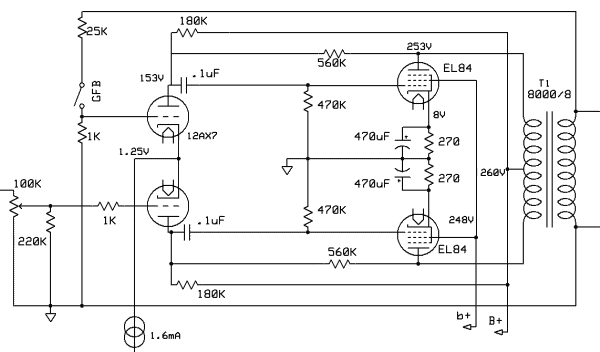
I tried to make an EL84 PP amp with the shunted partial feedback, a'la Yves' ECL84PP and Gingertube's Baby Huey as described in post#1, but did not achieve satisfactory [measured] performance.
A better solution:
I have now rewired the amp again to separate the load and feedback resistors. This gives much better performance.
Distortion without GFB is about 0.35% at 1W, and max power of ~8W is reached with a couple of %. Output impedance is ~6 ohm which means it can be used without GFB.
The modified schematics:

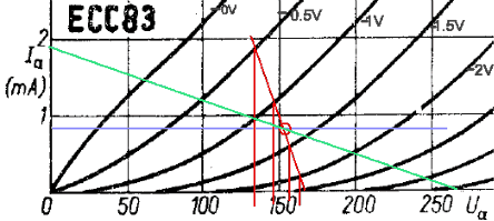
As disscussed earlier in this thread, the partial feedback scheme presents a difficult load to the driver tube. Here is my present operating point and estimated load-line:

Amplification factor of the ECC83 is degenerated to about 20, confirmed by measurements.
I suspect that the shunted FB scheme requires high quality OPTs with very good symmetry and low leakage inductance to give the desired results. The separate load/fedback is less critical in this respect. The topology now looks a bit like two RH84s back-to-back.
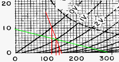
It has been suggested to use ECC81 (12AT7) as driver tube for better performance. A rough estimatee of the load-line for the RH84 does however also look rather steep for a triode load. I have not tried this yet.

Sorry for re-awaking an old thread, but i wanted to share my findings so far.
SveinB.
I tried to make an EL84 PP amp with the shunted partial feedback, a'la Yves' ECL84PP and Gingertube's Baby Huey as described in post#1, but did not achieve satisfactory [measured] performance.
A better solution:
I have now rewired the amp again to separate the load and feedback resistors. This gives much better performance.
Distortion without GFB is about 0.35% at 1W, and max power of ~8W is reached with a couple of %. Output impedance is ~6 ohm which means it can be used without GFB.
The modified schematics:

As disscussed earlier in this thread, the partial feedback scheme presents a difficult load to the driver tube. Here is my present operating point and estimated load-line:

Amplification factor of the ECC83 is degenerated to about 20, confirmed by measurements.
I suspect that the shunted FB scheme requires high quality OPTs with very good symmetry and low leakage inductance to give the desired results. The separate load/fedback is less critical in this respect. The topology now looks a bit like two RH84s back-to-back.
It has been suggested to use ECC81 (12AT7) as driver tube for better performance. A rough estimatee of the load-line for the RH84 does however also look rather steep for a triode load. I have not tried this yet.

Sorry for re-awaking an old thread, but i wanted to share my findings so far.
SveinB.
- Status
- This old topic is closed. If you want to reopen this topic, contact a moderator using the "Report Post" button.