In the regulator, can I use an 11nm80 instead of the '840? It's an 800v n channel mosfet.
In the case of this particular shunt regulator, different output Mosfet types usually worked without oscillation but not with the original design's intended phase margin or effective low Zo HF extension when with different than IRF840's parasitic capacitance specs. It takes comparative simulations in Spice observing the open loop gain curve etc. to can estimate performance beyond pure guesswork about possible active parts substitutions. If you have that 800V NMOS already it may happily work in the 840's position but I can't guarantee that.
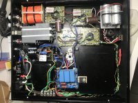
So, I'm making some progress on the deluxe 6v6 preamp. See post.
This is my first non-circuit board amp. Quite a challenge. I'm running out of room!
Got the gain stage mostly wired up. Will test soon
I'm using a 90uF output cap on the CF, because I want to double as a headphone amp (have some 600 ohm cans). I'm aware of the possibility of a turn on/off thump, but we'll see. I'm using a Neurochrome 21st century Maida, and with that + GZ34, I measured a full 30 seconds before it reaches full B+. Hopefully that will help.
Attachments
Thanks!
I also just realized that I used 2 X 15K resistors on the gain version rather than 2 X 10K as you have in your first post. I think I got that from someone who posted a variation.
Will that mess up the operating point much?
Maybe I can find another resistor to tack on in parallel.
I've got 340V, but can adjust that- although I have the CF version to keep in mind
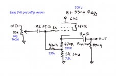
It can work with 7.5k plate load at an operating point of about 20mA Ip. But on 300V B+ also to keep things in proportion. The bottle runs cooler with less THD. The hotter standard configuration gives higher 2nd harmonic. Your subjective choice.
For a corresponding CF version with 7.5k and 300V B+ you should do like this:
For a corresponding CF version with 7.5k and 300V B+ you should do like this:
Attachments
Success! Kind of......
So, I managed to find a few resistors to make 5K on the plates- (2) 20K and (1) 10K 5W each in parallel, so I'm good there.
And I hooked up the gain stage, and it works! about 5X gain looking at the scope. I plugged into a super cheap amp and speaker just to see what it sounds like. Hey, pretty good!
But as I put my ear to the speaker, I'm hearing a short pulsing about 5-10 a second.
I also tried plugging the line amp into another better amplifier, this one, and with this amp the pulsing is very loud, a little slower, and I'm getting no audio signal to play at all.
I looked up this kind of sound, and I think maybe it's motor boating? Is it? I never experienced it before.
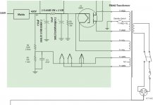
I did the power stage similar to a Tubelab SSE, since that is what I was successfully running in this chassis previously with JJ6v6s tubes. But I added a neurochrome 21st century maida. 430V and 335V out. See attached.
I'm also getting a fair amount of hum, but maybe that's to be expected since I didn't do DC on the heaters (yet). I'm elevating them as per the tubelab PSU schematic.
Also, some notes- I'm using 1uF output caps into 1 Meg resistors as per the original schematic. Tubes are JJ6v6s that I'm just using to test. I have some Tung Sol reissues on the way.
Thoughts?
So, I managed to find a few resistors to make 5K on the plates- (2) 20K and (1) 10K 5W each in parallel, so I'm good there.
And I hooked up the gain stage, and it works! about 5X gain looking at the scope. I plugged into a super cheap amp and speaker just to see what it sounds like. Hey, pretty good!
But as I put my ear to the speaker, I'm hearing a short pulsing about 5-10 a second.
I also tried plugging the line amp into another better amplifier, this one, and with this amp the pulsing is very loud, a little slower, and I'm getting no audio signal to play at all.
I looked up this kind of sound, and I think maybe it's motor boating? Is it? I never experienced it before.
I did the power stage similar to a Tubelab SSE, since that is what I was successfully running in this chassis previously with JJ6v6s tubes. But I added a neurochrome 21st century maida. 430V and 335V out. See attached.
I'm also getting a fair amount of hum, but maybe that's to be expected since I didn't do DC on the heaters (yet). I'm elevating them as per the tubelab PSU schematic.
Also, some notes- I'm using 1uF output caps into 1 Meg resistors as per the original schematic. Tubes are JJ6v6s that I'm just using to test. I have some Tung Sol reissues on the way.
Thoughts?
Attachments
Ok, heater lift removed.
So with my cheap Fosi test amp, the pulsing seems to be gone now- not sure how. From removing the heater lift?
But going into the hypex, the pulsing is still very very loud. I tried to scope it out, with 5mv, 10X, AC coupled as you mentioned, but I can't really make out a repeating pulse oddly. I tried all the time/divs too, and it's hard to tell. My scope is from the 70's and maybe not up to the task.
I should mention that the hypex amp has an RC network (100nF, 100 ohms) on the input ground to earth as per application note in section 4.5 of page 5 here.
Not sure if that has anything to do with it, just making sure I'm not leaving out any vital info.
I also realize that the pot is adding a lot of the noise to the mix as well. It's this one, 100K:
Audio Note 100K Stereo Volume Potentiometer Log (audio) Taper Solder Lug
60 cycle noise when the pot is in the middle position, but a lot less when at max or min.
I guess I have a ground loop too....
Audio Note 100K Stereo Volume Potentiometer Log (audio) Taper Solder Lug
60 cycle noise when the pot is in the middle position, but a lot less when at max or min.
I guess I have a ground loop too....
I never grounded the center tap of the 6.3 when I had the heaters lifted bit I can do that now. I can try disconnecting the buffer side easy enough. Also I think the pot noise is not just hum but also a lot of buzzing. I notice when I put my hand near the wires from the pot to the tube grid that it gets a lot louder. Maybe I should have used shielded wires for that?
This is separate from the oscillation issue though right? What do you think is causing that?
The amp is my workspace not my house so it'll be a few days till I get back to it. But thank you so much for your help! It was kind of a tough build, and has a few kinks but I know it'll get sorted out.
This is separate from the oscillation issue though right? What do you think is causing that?
The amp is my workspace not my house so it'll be a few days till I get back to it. But thank you so much for your help! It was kind of a tough build, and has a few kinks but I know it'll get sorted out.
It was kind of a tough build, and has a few kinks but I know it'll get sorted out.
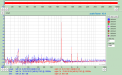
Mine is not the best arranged example and it measures like this in buffer mode. No audible buzz (100Hz and its harmonics). Left channel is bit worse because closer to the transformer. Uses the originally published constant current source DC heaters which are chassis grounded at one end.
Chart is with Russian 6Π6C, on RCA measures lower THD.
So you will fix it too. Nothing inherently unstable in it.
Attachments
The pot's body is actually entirely plastic, except the retaining washer and nut.The pot's metal case must be connected to signal ground for one. Else it buzzes to the touch.
Also the chassis must be referred to signal ground. Better via a 10 Ohm loop breaking resistor.
But, after the pot the signal goes to a switch, which sends to either buffer or gain stage, so that might be something to consider.
Will try redoing the signal ground via a loop breaker. I have a .22uf 750V X2 rated cap that I can put in parallel with the resistor as well. Right now, signal ground connected directly to chassis at one point. Chassis is then connected to earth, at IEC inlet.
Also, the JJ6v6's are crazy microphonic. Even if I bring a small LED flashlight near the tubes, I get high frequency noise. I have the tube sockets mounted to isolation standoffs, and works great, but I think these tubes seem super noisy. Tapping lightly on the tube is incredibly loud in the speakers. Will try the tung sols next week when they come in.
Hi Tom,
I do not have any additional decoupling after the maida. What values do you recommend? I'm assuming as close to the maida output as possible? Maybe that's part of the problem. After the maida, I have a twisted pair of wires that goes all the way to the tube sockets, around 6" of wire.
When you say at the input stage, do you mean between B+ and signal ground, but just physically closer to the input?
I do have a scope, but it's seriously old and kinda sucks. I tried scoping it, but for some reason I'm not seeing the pulses. I put at 5mv/div vert, and tried all the periods, but maybe since they're relatively slow around 10hz, they're hard to see with the slow scan.
Do you have supply decoupling locally at the power stage and at the input stage?
Are you able to put a scope on the supply voltage?
Tom
Last edited:
I do not have any additional decoupling after the maida. What values do you recommend?
Something like 1-10 uF film cap from B+ to ground at each amplifier stage.
I'm assuming as close to the maida output as possible?
No, actually. You want it as close to the amplifier stage as possible. You're trying to combat the series inductance of the wiring to your amplifier stages (and series resistance in case of motor boating).
I do have a scope, but it's seriously old and kinda sucks. I tried scoping it, but for some reason I'm not seeing the pulses. I put at 5mv/div vert, and tried all the periods, but maybe since they're relatively slow around 10hz, they're hard to see with the slow scan.
If the thumping is 10 Hz, you should be able to see it on the scope just fine. Start by scoping the output of the amp. You should see thumping there. Once you have the scope dialled in, poke at the B+ (with the appropriate probe and safety measures in place).
I'm not looking for a precision measurement here. It's more of a "does the B+ show the thumping?" type of question. Although, it sounds like the answer to that is "no" as you mentioned you didn't see any variation in the B+ even on the 5 mV/div scale. So it's probably not the Maida Regulator that is causing your trouble.
Which value do you have for R3 in the Maida? Looks like 30 Ω in the image you emailed me. That should allow for 120 mA peak. That sounds like plenty for a preamp, but it would be worth checking to see if the circuit draws more than that - in particular on startup.
Have you run the amp without the Maida? If you have a variac, you can dial the B+ to its nominal value by adjusting the applied mains voltage. You'll get lots of hum, I'm sure, but it would be interesting to see if the thumping goes away. If the thumping is there without the Maida Regulator in the circuit, the problem is in the rest of the amp and unrelated to the Maida.
Pardon my initial question with input/output stage. I think my brain provided an auto-response intended for power amps.
") I see you're working on a line amp.
I see you're working on a line amp.Tom
Last edited:
Ok, so good news, and some bad news.
First the good news:
I made the following changes to the grounding scheme:
Back to what I was thinking was motorboating.....
Put the scope on again, and I can see a little jump registering in sync with the pulsing when I put on the output. But not on the B+.... (clue)
Tested with 2 amps, a $20 junky thing I picked up on Ebay, and a very nice Hypex class D. The junky amp noise was way down, and no pulsing. Must have input caps. Sounded pretty good! Plugged it into the Hypex and the loud pulsing was still there. ??
I had tested the signal outputs before, but I think I had the scope on AC coupled. Switched to DC coupled. What???? 25VDC on one output, 30V on the other!!
This is through a 1uF Jupiter cap. 1M ohm bleeder between signal and ground, right at the RCA connector.
Looks like I was sending a ton of DC into the Hypex. So my ground scheme could have used some improvement, which I fixed, but the DC on the output must be the real issue. I could have easily damaged my amp. Maybe it was going into some kind of shutdown mode or something. Fortunately, I think it's ok.
So, I have some 3.9uF film caps laying around, so then took out the jupiter, and replaced it with this. I put the multimeter on the output (without it connected to the amp), and as the B+ grows, the signal output goes from 0 to 100V then gradually down to about 5V then 1V, then settles to around 300mV or so. 1M must be too big of a bleeder, so I can change that later. Or get a smaller, different output cap. I did get them second hand, maybe they're just bad? The other side of the jupiter read 335V, so they are blocking some DC, but not all?
Anyway, this is a good stopping point today. A learning experience!
Maybe I stick with the 3.9uF output caps, and put a 100K bleeder in there?
Whew!
First the good news:
I made the following changes to the grounding scheme:
- Put a 10R||220nF loop breaker between ground and earth
- Installed several .47uF/600V polyprop caps between B+ and gnd at various points near the tubes
- Connected 6.3 winding CT to gnd
- Wow, HUGE difference in noise. Way quieter....
Back to what I was thinking was motorboating.....
Put the scope on again, and I can see a little jump registering in sync with the pulsing when I put on the output. But not on the B+.... (clue)
Tested with 2 amps, a $20 junky thing I picked up on Ebay, and a very nice Hypex class D. The junky amp noise was way down, and no pulsing. Must have input caps. Sounded pretty good! Plugged it into the Hypex and the loud pulsing was still there. ??
I had tested the signal outputs before, but I think I had the scope on AC coupled. Switched to DC coupled. What???? 25VDC on one output, 30V on the other!!
This is through a 1uF Jupiter cap. 1M ohm bleeder between signal and ground, right at the RCA connector.
Looks like I was sending a ton of DC into the Hypex. So my ground scheme could have used some improvement, which I fixed, but the DC on the output must be the real issue. I could have easily damaged my amp. Maybe it was going into some kind of shutdown mode or something. Fortunately, I think it's ok.
So, I have some 3.9uF film caps laying around, so then took out the jupiter, and replaced it with this. I put the multimeter on the output (without it connected to the amp), and as the B+ grows, the signal output goes from 0 to 100V then gradually down to about 5V then 1V, then settles to around 300mV or so. 1M must be too big of a bleeder, so I can change that later. Or get a smaller, different output cap. I did get them second hand, maybe they're just bad? The other side of the jupiter read 335V, so they are blocking some DC, but not all?
Anyway, this is a good stopping point today. A learning experience!
Maybe I stick with the 3.9uF output caps, and put a 100K bleeder in there?
Whew!
- Home
- Amplifiers
- Tubes / Valves
- 6V6 line preamp