")
OK-- so I'm going to tweak a bit this weekend. I was expecting this to be more than powerful enough for my Fostex 206E backhorns (96dB 1W / 1M), particularly since my 2A3 Bottleheads with a Foreplay linestage will blow the back off the house. However, I am currently cranking these motherfathers (around 3:00 listening position on the dial) to get a deep volume of sound.
Granted, the 2A3s have a preamp and the DRD is on a 5K primary, but I still thought I'd have more headroom.
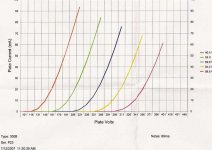
Anyway, I was going to adjust the bias resistor a bit when I looked at the plate curves that came with the TJ Meshplate 300bs and they seemed a little off.
Take a look at the attached and let me know what you think. I was expecting that these curves would be strikingly similar to other 300bs, but it appears that for 60mA of current, I would need to have a g-k of closer to -90V instead of the -72V in the DRD schematic.
Am I looking at this wrong or is the meshplate behaving differently?
As Sheldon has recommended, I will measure the voltage drop / resistance of the bias resistors to make sure I'm on target, but I'd like to know why these curves seem different.
Kofi
Granted, the 2A3s have a preamp and the DRD is on a 5K primary, but I still thought I'd have more headroom.
Anyway, I was going to adjust the bias resistor a bit when I looked at the plate curves that came with the TJ Meshplate 300bs and they seemed a little off.
Take a look at the attached and let me know what you think. I was expecting that these curves would be strikingly similar to other 300bs, but it appears that for 60mA of current, I would need to have a g-k of closer to -90V instead of the -72V in the DRD schematic.
Am I looking at this wrong or is the meshplate behaving differently?
As Sheldon has recommended, I will measure the voltage drop / resistance of the bias resistors to make sure I'm on target, but I'd like to know why these curves seem different.
Kofi
Attachments
Kofi, it's simple and very informative to just measure the voltage relative to earth at each point is the circuit. Then all we have to do is ask Ohm what is going on.
No personal experience with various 300b tubes, but it wouldn't be a shock to find significant differences. I doubt , however, that those differences would amount to more than a couple or three dB.
As to the attitude of the volume control, it's a measure of sensitivity not necessarily power. The measure of power is not where the dial sits, but how loud you can go before distortion becomes excessive. As long as you source can drive it to that point, you're fine. In fact, I like to set things up so that I can crank the source all the way up and just start to get distortion.
Sheldon
Blowing Fuses!
Here's your typical Red Alert Message:
So, last night I'm listening to Ornette Coleman and I hear a popping in the left speaker during the transients. I find a bit of dust on the needle, so I think nothing of it, shut down and go to bed.
This morning, I get up and no power in the left channel-- blew the fuse. I replaced the fuse and I saw a sparking in the rectifier tube, then the fuse blew again.
So, I figure it must be the $7.00 Valve Art 274b, so I replace it with the other one and same problem-- blown fuse. So, back to the workshop I go. I notice that there's no voltage in the PSU caps, which is bad since they usually retain about 250V or so after a power up.
Nothing is burned and nothing smells funny except for me, so I power up again to test the voltage across the caps and there's a few volts (5 or so), then nothing, then a few volts (again, 5 or so), then the fuse blows. I'm guessing this implies that the PSU sees the tubes since it's probably up-down-up due to the heater warm-up.
I am currently checking for ground continuity on stuff that ain't supposed to be grounded, but I'm getting scared that either one of the oil caps has had it or there's an overheated / shorted winding on a piece of iron.
I also checked the transformer secondary and (here's the part where you tell me I'm out some dough) the 0V is at ground (good) and the 8R tap is ALSO AT GROUND (BAD, right?). In other words, I'm checking continuity with a 1.5K resistor and both the 8R and 0V secondary taps register 1.5K with the black lead of my DMM tied to ground and the resistor between the tap and the red lead.
Well, I'll keep looking to see what's up, but I really need some help here in the diagnosis.
Help me, please!
Kofi!
Why the 1.5K resistor to measure your secondary DCR? In any event, you have one nice tool in this situation. You have an identical amp that works. So, measure resistance/continuity at each point in the good one and compare with the problem unit. That should isolate the problem area.
Sheldon
Sheldon
Good point, of course.
I need a shower and some food, so I'll report back after diagnosis.
In the interest of full disclosure, the rectifier on this monoblock was sparking when I had first finished it as I had accidentally crossed some wires. I shut it off immediately, found the fault and powered back up to a perfectly working amp.
Now I wonder if I had weakened the tube during this period, causing it to arc during an extended listening period last evening. I'm speculating that this could have sent some rather nasty B+ spikes across some components that really don't like that-- maybe the OPT.
Yikes.
More after I compare and contrast the two amps. Thanks so much for the response.
Kofi
Looks like I found the culprit.
Tell me what you think, but Kofi thinks his 20H common-mode choke is fried.
So, I checked continuity and I found that I had 108 ohms of resistance between the + terminal on the 4uF PSU cap and ground on the bad amp compared to no such thing on the good amp.
Hmmm...
I pulled the 20H choke and I found that there's exactly 108 ohms of resistance between the orange and red leads, which are supposed to be on separate windings. Looks like a shorted turn, right?
So, here's my theory:
The effed up rectifier that I stuck with after the initial incident (see previous post, above) was probably arcing and sending B+ spikes through the 4uF cap and the 20H choke, heating and ultimately shorting the windings. This caused the B+ to be shunted to ground via a 108R resistor, effectively, which blew the fuse.
OK-- so if you agree with me here, this may not be all bad. I am going to order the Lundahl units that were recommended by Thorsten in this design as replacements. Apparently, the Lundahls had a common-mode mode that was much desired as a hum-reducer, which the bi-filar jobs wound by Jack did not.
Any corroboration of my diagnosis would be much appreciated. I think this is the ticket, but I always like to be sure.
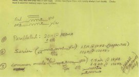
Attached is Jack's scrawl he supplied with his transformers. I believe this indicates that there should be no continuity between the orange and red leads, but you know you gotta check me, right?
Thanks again for the help.
Kofi
Tell me what you think, but Kofi thinks his 20H common-mode choke is fried.
So, I checked continuity and I found that I had 108 ohms of resistance between the + terminal on the 4uF PSU cap and ground on the bad amp compared to no such thing on the good amp.
Hmmm...
I pulled the 20H choke and I found that there's exactly 108 ohms of resistance between the orange and red leads, which are supposed to be on separate windings. Looks like a shorted turn, right?
So, here's my theory:
The effed up rectifier that I stuck with after the initial incident (see previous post, above) was probably arcing and sending B+ spikes through the 4uF cap and the 20H choke, heating and ultimately shorting the windings. This caused the B+ to be shunted to ground via a 108R resistor, effectively, which blew the fuse.
OK-- so if you agree with me here, this may not be all bad. I am going to order the Lundahl units that were recommended by Thorsten in this design as replacements. Apparently, the Lundahls had a common-mode mode that was much desired as a hum-reducer, which the bi-filar jobs wound by Jack did not.
Any corroboration of my diagnosis would be much appreciated. I think this is the ticket, but I always like to be sure.
Attached is Jack's scrawl he supplied with his transformers. I believe this indicates that there should be no continuity between the orange and red leads, but you know you gotta check me, right?
Thanks again for the help.
Kofi
Attachments
Sorry for the delay...
The DCR is around 270R and I can clearly see that there's a shorted winding and I think I know how it happened.
It looks like the orange lead had a cut in the insulation and got shorted against the B+. I ain't no engineer, but I'm guessing that would do it.
So, do you think my rectifier is hosed or can I try and use it again? I ordered another pair, but they probably won't be here until next week and I wanna listen now!
Yours in impatience,
Kofi
OK-- so I installed the Lundahl common-mode chokes and had a listen. The sound was very different-- softer with not as much gain. So, I figure it's a voltage problem, right?
I had to readjust the trimpot to lower the d3A anode / 300b grid voltage to about 177V (it was about 205V after the choke install) and things seemed about normal, but now the B+ is too high-- the 300b is seeing 375V instead of 350V, which I'm concerned is too high.
Also, the 1K cathode resistor (which measures .995K) is dropping 68.5V, which means it's passing almost 69mA of current.
I'm still taking some measurements, but it seems that the additional B+ is causing some problems. I may need to add a resistor in series with the B+ to drop some voltage, right?
Any suggestions?
Kofi
At the risk of sounding like a broken record, it would be most instructive to show us your schematic with all the actual node voltages indicated. Before and after would be even better. Here's an example:
http://www.diyaudio.com/forums/showthread.php?postid=1322965#post1322965
Meantime, the voltage changes you see are not necessarily alarming. The new choke might have much lower DCR, but without the whole picture?
Sheldon
http://www.diyaudio.com/forums/showthread.php?postid=1322965#post1322965
Meantime, the voltage changes you see are not necessarily alarming. The new choke might have much lower DCR, but without the whole picture?
Sheldon
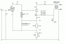
Here you go. The bolded figures that don't have a "V" after them are my measured voltages.
Still puzzled as to why it looks like I'm running at 69mA, though.
Anything jump out at you as particularly fishy here?
Thanks for your help.
Kofi
Still puzzled as to why it looks like I'm running at 69mA, though.
Anything jump out at you as particularly fishy here?
Thanks for your help.
Kofi
Attachments
Looks fine to me Kofi. The bias current is as you calculated. I don't know what the dissapation limit you want on the output tube, but based on a cursory check, it seems you are well within the ratings. But double check that.
If you want to lower the current, you have several options. Easiest is to adjust the voltage at the grid with your lower pot. Or you can increase the other resistor values in series with the 300b cathode. I'd try the simple adjustment first. Then look at the curves for the input tube to make sure you are still in a nice linear region. And listen.
These kind of designs are a bit tricky because all the voltages are interdependent. But as long as you are in safe dissapation areas, play at will.
If you want to reduce ps voltage, I wouldn't use series resistance . A much better approach would be to reduce the size of the power supply input cap.
Sheldon
Kofi,
Its a tube amp - that means +/- 20% on voltages - those voltage readings are fine.
Quick Calcs:
265-197 V across that 1K in the cathode.
That means 68mA and therefore also -68V bias from grid to cathode
644 - 265 = 379 V Anode to Cathode.
At 68mA that gives 25.8W Anode dissipation - a good conservative place to run the 300B.
Extrapolating off the 300B data sheet that operating point should be giving you about 8 watts of audio out.
Unless you are somehow unhappy with the sound I'd say its finished - sit back and enjoy.
Cheers,
Ian
So, after years of gathering parts and convincing wives......
Kofi
Hey! you live in Utah?
Hey! you live in Utah?
No, way from Cedar City: in Russia.
- Status
- This old topic is closed. If you want to reopen this topic, contact a moderator using the "Report Post" button.
- Home
- Amplifiers
- Tubes / Valves
- Kofi Annan in: "Kofi Makes a 300b DRD... and You Get to Help!"