The transformer work on 230VAC my region works on 220VAC.
We have 0,220VAC, Ground so what do I connect to 0 and what to Ground?
Can I connect all 0V on all the taps?
I saw the you connected the 0ohm of output transformer to Ground, why?
One last question, when I used 500mA slow blow fuse it blow, why? (After that I used 1A,OK)
thanks
Ran: So your region is 220VAC and the transformer only has a 230V primary?
If so, that would explain the low secondary voltages.
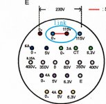
Can you post a picture of the taps on the power transformer?
For the sake of testing, you can tie your earth ground to the E terminal of the power transformer. Use your ohm meter to convince yourself that the E terminal is connected to the transformer case.
It's a good idea to ground the common side of the speaker terminals/output transformer so they are not floating. Some speakers require this, like vintage Polk SDA's etc.
"Can I connect all 0V on all the taps?".......I don't understand this question.....
What shell I do about the low voltage?
The E tap is not connected to the case.
As you can see in the picture attached there are many 0V, and because I what to put the PT in different case I what to have as less wires in the cable between the PT and the amplifier case.
The E tap is not connected to the case.
As you can see in the picture attached there are many 0V, and because I what to put the PT in different case I what to have as less wires in the cable between the PT and the amplifier case.
Attachments
OK, it's clearer now.
Looks like your transformer will only do 230V mains, and you have 220V mains. Your secondary voltages should be lower to approx 220/230=95.6%......
so 6.3*.956=6.02V
5*.956=4.78V
What is the actual measured mains voltage from your house? (check very carefully!)
I understand your question about the ground connections now, how many do you need to run in the umbilical......
I ran one for the 5V rectifier, one for the 6.3V filament, and one for the CT/chassis ground (originally combined). IIRC, that gave some hum and I ended up running a separate ground for the CT and the chassis, so I have 9 conductors HV, CT, HV, 5V, 5V(E), 3.15, CT, 3.15, chassis ground.
Re-check the E terminal to a mounting screw, it's grounded on my 9611 transformer.
To get the voltages up, you can "buck" or "boost" the windings. Very roughly, you can wire say an extra 5V or 6.3V winding in with some of the other windings to add or subtract a little voltage.
I will ask one of the experts here to chime in, hopefully Eli D or Tubelab George can help you out.
Ran: I did a little research on bucking and boosting transformers......you may want to do the same.
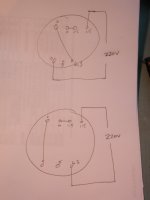
Since you have extra 5V and/or 6.3V windings you can simply wire an extra 6.3V winding in series with your primary winding to buck or boost the secondaries, depending on the phasing of the windings. If the output voltages are lower, then you need to flip the polarity of the 6.3V winding wired in series with the primary.
So you will either end up with a 230-6.3V=223.7V primary or a 230+6.3V=236.3V secondary. If you have a few unused taps, you can get even more creative, like wiring two unused 5V taps in series with your primary winding to get to 220V.
Be sure to do this test with a fuse fitted......I can draw a diagram if you need one. Keep in mind that this wiring reduces the isolation between your primary and secondary windings.
I can also experiment here with a cheap power transformer, as I'm always up for learning something new.
First, again Thanks for your quick replays 
Yes, it would be very happy if you could draw for me the schematic you just suggested.
And yes, it will be must appreciated if you can test it yourself too
Does a 1A slow blow fuse will be fine?
About the 0V for the cable, I will do as you did, one for every voltage.
Yes, it would be very happy if you could draw for me the schematic you just suggested.
And yes, it will be must appreciated if you can test it yourself too
Does a 1A slow blow fuse will be fine?
About the 0V for the cable, I will do as you did, one for every voltage.
Ran: I just connected an old Hammond transformer in buck/boost config by wiring the 6.3V filament winding in series with the primary....here are the results:
normal connections:
HV-0=394VAC
5V=5.33VAC
6.3V filament windings in series with primary 115V windings: (boost)
HV-0=420VAC
5V=5.64VAC
Reverse polarity (phasing) of the filament windings (buck)
HV-0=374VAC
5V=5.06VAC
See attached pic for your two possible wiring configs. Please test with a fuse fitted and post the results.
Since you have lots of filament windings, if 6.3V boost is not enough I imagine that we can mix and match a few more windings to get higher voltages, like a pair of 5V windings for 10V or a 5 and a 6.3V for 11.3V boost. It's just a matter of proper phasing.
Ranhaber: I've just posted another thread in the tubes forum: http://www.diyaudio.com/forums/tube...sting-tube-power-transformer.html#post3520482
Attachments
Last edited:
Last night I measured on the HV 350-345VAC. it's strange that the HV didn't changed like the 5V
I'll try to connect the winding like you suggested later this evening, but...
What are the cons' for the long run on such improvisation?
The first "cons" that I can see is that my HV will be larger and hope that the 5V tap will rise more then yours
Ohh I almost forgot to ask you, did you meant that the E must be shorted to the black cover of my 9612?
Will post my result ASAP
Last night I measured on the HV 350-345VAC. it's strange that the HV didn't changed like the 5V
I'll try to connect the winding like you suggested later this evening, but...
What are the cons' for the long run on such improvisation?
The first "cons" that I can see is that my HV will be larger and hope that the 5V tap will rise more then yours
Ohh I almost forgot to ask you, did you meant that the E must be shorted to the black cover of my 9612?
Will post my result ASAP
Ran: Have you subscribed to this thread? http://www.diyaudio.com/forums/tube...sting-tube-power-transformer.html#post3520629
A couple of the "cons" will be that you are driving the transformer closer to saturation, although in this application, I think you have plenty of headroom. You also lose a little electrical isolation since we are now tying the primaries to some of the secondaries.
As far as the E terminal goes, you were asking about it earlier; it should be a ground, and connected to the case. When you build the chassis, it's a good idea to tie it to chassis ground for safety.
Is funny that one man problem is second man entertainment
I have read the thread you opened, the only thing I didn't understood was, how do lower isolation effect the PT or the Amp in general?
And about the E, Oops I apologize for the foolish question
 must be the late hours
Is funny that one man problem is second man entertainment
I apparently have no life
I have read the thread you opened, the only thing I didn't understood was, how do lower isolation effect the PT or the Amp in general?
Well, using the transformer right out of the box means that the primaries and secondaries are not physically connected to each other, they are inductively coupled through the transformer core, so there is no way that your mains current (say up to 20A or however large your home circuit breaker is) can get to the secondary side of the transformer.
Wiring the 5V or 6.3V winding from the secondary into the primary now ties windings on both sides of the core together. You only have the insulation/varnish on the windings separating the mains from the secondary side.
grounding TSE
I have two problems that may be related:
1. Again, I have 0, 220, Ground. What do I connect to T1-1, 0 or earth/ground? And the same question to all "gnd" symbols.
2. I connected all of them to earth/ground and don't have any voltage on R30 or R7, does it because of question 1?
Thanx
I have two problems that may be related:
1. Again, I have 0, 220, Ground. What do I connect to T1-1, 0 or earth/ground? And the same question to all "gnd" symbols.
2. I connected all of them to earth/ground and don't have any voltage on R30 or R7, does it because of question 1?
Thanx
Hello Ran,
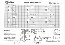
according to schematics T1-1 seems to be center tap of power transformer high voltage secondaries:
http://www.diyaudio.com/forums/tubes-valves/126672-tubelab-wiring.html#post1566248
I attached tse wiring layout, that someone posted some time ago - could not find link to the post where I found it, hopefully, someone more knowledgable than me will confirm that it is ok.
I did not finish this project - just about time when I wanted to populate board, my soldering station went bust and I did not bother to buy another one until now (I like sound of my SSE). Your post motivated me to order same set of James transformers as you did and hopefully in some time I will finish my tse.
Attachments
thanks zxx,
Now i understand my mistake, i saw the grd symble and connected all of them to earth/ground.
I'll fix that and try it as soon as i get home.
After 16 hours of work every day the mind is not the same .
.
p.s.
Try to order the transformers from the company itself like i did. It's cheaper.
Thanks again
Now i understand my mistake, i saw the grd symble and connected all of them to earth/ground.
I'll fix that and try it as soon as i get home.
After 16 hours of work every day the mind is not the same
.p.s.
Try to order the transformers from the company itself like i did. It's cheaper.
Thanks again
" And then shall your light break forth"
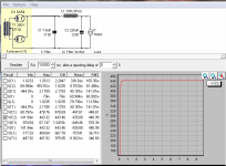
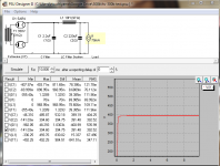
The first check is done and the rectifier had lightened, but
I used 7.6uF as C4,
James chock with 97ohm 10H,
220uF C5.
The voltage I measured were:
R30 was 470V,
How can it be? When I simulated it in PSUDII R30 supposed to be 390V.
I'm planning on using 300B tubes.
R7 was -290V. Is that, ok?
The first check is done and the rectifier had lightened, but
I used 7.6uF as C4,
James chock with 97ohm 10H,
220uF C5.
The voltage I measured were:
R30 was 470V,
How can it be? When I simulated it in PSUDII R30 supposed to be 390V.
I'm planning on using 300B tubes.
R7 was -290V. Is that, ok?
The voltage I measured were:
R30 was 470V,
How can it be? When I simulated it in PSUDII R30 supposed to be 390V.
I'm planning on using 300B tubes.
R7 was -290V. Is that, ok?
-290V for the bias is normal with 300B's.
As evanc asked, was the B+ measured without the tubes installed? When the tubes are drawing current, the B+ voltage will come down.
Do you happen to have access to a variac to do the initial power-up? That reduces a lot of the white-knuckle factor.
-290V for the bias is normal with 300B's.
As evanc asked, was the B+ measured without the tubes installed? When the tubes are drawing current, the B+ voltage will come down.
Do you happen to have access to a variac to do the initial power-up? That reduces a lot of the white-knuckle factor.
The B+ measured with only the rectifier tube 5ar4 plugged.
No access to variac.
If I understand you right, I can now continue the test and plug in the rest of the tubes...
- Status
- This old topic is closed. If you want to reopen this topic, contact a moderator using the "Report Post" button.
- Home
- More Vendors...
- Tubelab
- Tubelab SE