I would like to push beyond the 14 watts
The Antek has shipped, but I don't have it yet. I hooked the two power supplies up to the board in the same manner that I did with the EL84's but popped in 4 of my GE 6CW5's. I can report that these guys can operate at levels significantly above the specified maximums without exploding. I saw over 30 WPC flowing out of my amp without frying the tubes but the current meter needle was buried and the cathode resistors (old board 2 watt resistors) look a little brown now. I may install the 5 watt resistors tomorrow if I have time, but I wouldn't recommend going much over 25 watts. More tesitng tomorrow. It's too late to play with electricity any more tonight.
I got 19 NOS Siemens 6CW5's off ebay for about $2 each.
All I could find on Ebay was overpriced junk. I can get NOS GE's for $5 each, maybe less if I buy a few, but I have a box full of pulls that seem to put up with my torture. I haven't blown one yet.
What is an acceptable level of abuse?
Slight red plate at the seam of the two plat halves when viewed with all lights out?
It depends on your definition of "acceptable". If your intent is to abuse the tubes and finish them off in a relatively short period of time, then what you observe will work perfectly fine.
My rule is zero visible red plate. If I can see even the slightest hint of red in a pitch dark room, then it is time to reduce the plate dissipation.
What is an acceptable level of abuse?
First it is important to consider the application, and its expected tube life. I have been known to light some tubes up so brightly that you could read by the plate glow. That was a one time experiment with some rather useless tubes, which don't seem to work so well any more (no surprise).
There are two possibilities to consider when exceeding the specs on any tube. The first is shortened tube life. If anything other than the cathode (and the filament) is glowing red inside the tube it will outgas ions which will contaminate the vacuum. Ionic contamination will casue increased distortion and grid current which can possibly lead to loss of control and a runaway condition. The hotter you run a tube, the quicker you will contaminate its vacuum. This applies even below the red zone. NOS tubes often have a better vacuum to begin with and used better quality materials that todays current production tubes.
Anything glowing is also capable of emitting electrons. This can create many unwanted effects caused by unexpected secondary emission currents. As I have found out some can be catastrophic to the tube and its supporting components. A glowing plate will emit electrons but there isn't anywhere for them to go in a pentode, so they don't cause much trouble. The biggest issue for red plate is vacuum contamination. A glowing screen is a possible death sentence for a tube under some conditions, and is generally bad under any conditions. In applications where the screen voltage is less than the plate voltage the electrons emitted from the screen will travel to the plate. I have seen this lead to a runaway condition that led to a violent tube arc wiping out the tube and several other components.
In anything built for unatended (you aren't watching the tubes) operation, I wouldn't venture into the red zone. I usually will find the red zone and back up a considerable distance if decent life expectancy is desired.
It is common to find tubes that display no hint of redness even when operated far in excess of the published ratings while another tube with the exact same number on it will glow brightly when operated BELOW its published ratings. This has been the case with the 6CW5. I have some that will not work at the published 12 watt plate rating, while last nights "crank em up" test with used GE tubes produced no hint of redness at 300 volts on the plate and 30 WPC output. I do not know the plate dissipation but I am sure that it was over 12 watts.
The data sheet for the 6CW5 does show a set of operating conditions that put out 25 watts. I can not get 25 watts of output power under these conditions, but I don't have a 3K ohm OPT.
Operation far in excess of voltage or dissipation specs raises the risk of catastrophic tube failure in an otherwise normal running amplifier, even if there is no visible glow.
Anyone who operates tubes in excess of the published specs must be prepared to accept whatever risk is associated with their level of abuse. Therefore the acceptable level of abuse varies with the expected use of the device and the risk tolerance of the user. I might have no problem running some cheap sweep tubes at nearly double their published ratings in an amplifier that I built with junk box parts (the red board) but I have never run my NOS GE 211's above 70% of their ratings.
Once these amplifiers are in circulation there will be enough users that push them hard enough to find out which 6CW5's can be cranked up and which ones can't. There are no new 6CW5's being made so this won't change. At this point there isn't much data on this little tube.
The problem arises when new production tubes are used that are not consistent. The Simple SE can use 6L6GC's. When I designed the amp the Shuguang coke bottle shaped 6L6GC had a reputation for being bullet proof. Indeed the pair that I used to develop the amp are still going strong. These tubes have been seen glowing brightly on the pages of this forum several times. The current batch of these tubes will exhibit plate glow at or below the published max for a 6L6GC, and some users have had trouble with them in their Simple SE.
George,
My plan is to build your Simple PP amp with a source selection switch for 3 or 4 sources and possibly a sub out for signal to a powered sub depending on the speakers used.
Is this all possible with your board? and is all of my switching and sub out done prior to the signal reaching the board input?
Thanks for your help.
Scott
To get an idea about external hook-up possibilities, I would have a look at the Simple SE instructions. I would expect them to be largely the same.
The concept is exactly the same. So are most of the external connections (except the OPT's have a few more wires).
This board can be operated in triode, UL, and pentode mode. There is no cathode feedback since that is very hard to get right on a P-P amp (requires good symmetry in the OPT), but Global Negative Feedback is available and connected up in the same manner as cathode feedback on the Simple SE. Although the Simple SE could be connected up in pentode mode, I only know of one user who actually did it. I expect that most users will connect this board up in pentode mode, or possibly UL. It will work in triode mode but it would get its butt kicked by a Simple SE, so why bother.
The connections are still present for an external choke and supplemental capacitor, but they don't make the same improvement that they did on the Simple SE. The nature of P-P and pentode operation cancels most power supply hum. The amp is very punchy and dynamic without them. These connections are useful for some other purposes that will be documented after further testing.
Is this all possible with your board? and is all of my switching and sub out done prior to the signal reaching the board input?
The input connections are exactly the same as the Simple SE. Any input switching and volume control circuitry is done off board before the signal gets to the PC board.
We had out first winter cold front blow through yesterday resulting in perfect amp building weather today (65 degrees and sunny). I spent the day outside completing the chassis work for Simple P-P amp number 1. The top plate and transformers are freshly painted and presently baking in the Florida sun. The wood pieces are sanded and oiled and will be glued up tomorrow.
The wood pieces are sanded and oiled and will be glued up tomorrow.
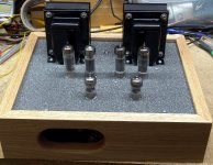
You know I couldn't wait that long. The paint was dry in an hour so I glued up the box and left it outside until dark. After dinner I started putting it all together. Here is two pictures of the progress so far. It has been almost two years since I have completed an amplifier. There are several half finished projects stashed here and there, but it looks like this one might really get finished.
Attachments
Your woodworking is improving.
Thanks. After 3 years of woodworking classes I have built a chassis without sheetrock screws or butt joints. 3 more years and I may be able to do dovetail joints.
But where did the supply tube go ?
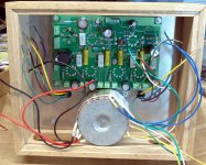
This amp uses 6CW5 tubes. They require less voltage and a lot more current than the typical rectifier tube can handle. This particular amp will be replacing my Industrial Simple SE for daily use. To keep it cool the B+ voltage is about 220 volts but the current meter hits 1/2 an amp when the amp is clipped. The usual 5AR4 will not work here, so it gets replaced with sand. The EL84 versions of the Simple P-P use the 5AR4 rectifier.
There are two tube sets that can be used in this amp. There are two different "builds" with each tube:
The 6CW5 / EL86 is a low voltage version of the EL84. It was designed for use in OTL audio circuits using an SRPP design and a 600 ohm speaker. It has been used as the audio output tube and the vertical (frame) output tube in TV sets. It is not being currently made, but they are widely available for low cost. It works well in conventional P-P circuits such as this one, but a low voltage high current power supply is needed.
The Antek power toroid used in this build is $29 and it is 120 or 240 volt capable. Solid state rectification is used. This allows for a good low cost amplifier. The maximum specified plate voltage is 250 volts and the screen grid spec is 200 volts in most data sheets. The amp shown here will be documented in the construction plans. It is a conservative design that operates the tubes within the published ratings and makes about 14 WPC.
I have a larger power transformer on order. Based on the testing results there may be an additional set of connection diagrams and a resistor value change to allow higher output power with capable 6CW5 tubes.
The 6BQ5 / EL84 is a 9 pin miniature tube that has been used for years as an audio output tube. It is in current production but costs considerably more than the 6CW5. There are multiple versions and substitutes for this tube. There is a wide variation in the power and voltage handling capabilities of these tubes. There will be two versions ot the Simple P-P to cover the EL84 type tubes.
The conservative version runs the tubes with about 350 volts of B+ and generates 14 to 15 WPC depending on the tubes and OPT's. A 5AR4 rectifier is used. It should work with most EL84 type tubes. This is the version covered in the construction manual.
I have a second amplifier breadboarded that runs with about 400 volts on the plates and 300 volts on the screens. This is WAY ABOVE the maximum ratings for the typical EL84. The true 7189A can handle these voltages, but they are rare and the relabled Russian substitutes will melt! The JJ El 84's that I have seem to be fine all the way up to 430 volts, but this may not be true of all tubes. This amplifier has incredible measured specs and sounds nice while cranking out nearly 20 WPC. I will publish the plans for those who wish to try it.
This particular amp will be replacing my Industrial Simple SE for daily use.
Being a generation behind with my SE fever prognosis going strong, that makes me a little sad.
")
Being a generation behind with my SE fever prognosis going strong, that makes me a little sad.
It's not like the Simple SE is going to face the executioner of something. I usually change amps fairly often and the Simple SE has been my main amp for over a year (the longest so far). That particular amp is built in an enclosure that is really a bit small and I have been running EH KT88's in it at a bit too much current. The amp throws off some serious heat (not good here even in winter), so its time for a change (out with the old picture tube TV too). The Simple SE is a fairly stable design and mine has been subjected to some serious testing. Other than a pair of blown FREDs (now replaced with Fairchilds) in the first week, it has been flawless. I think that this one is going to be my guitar amp for a while.
Just as we do with new phone designs, I intend to flog the new Simple P-P design heavilly just to make sure that it lives up to my standards.
It's not like the Simple SE is going to face the executioner of something. I usually change amps fairly often and the Simple SE has been my main amp for over a year (the longest so far).
Hehe...that was a mostly-tongue-in-cheek comment. Honestly, I will be building some PP amp with EL84s here at some point. I've had a bunch of components and tubes (quad of JJs and a quad of some Russian military spec tube) for one for about 10 years now. They were going to become a "Bevois Valley" amp, but that never happened once I got the old Thomas amp going. Later I thought about building an RLD. We'll see.
That particular amp is built in an enclosure that is really a bit small and I have been running EH KT88's in it at a bit too much current. The amp throws off some serious heat (not good here even in winter), so its time for a change....
Must be due to the power transformer? I've run mine at about 95ma with Reflektor 6550s and it barely gets warm. Mine is a giant heat sink, though, but the power transformer is barely breaking a sweat. The CCSs are tied to the chassis as are the main cathode resistors.
The Simple SE is a fairly stable design and mine has been subjected to some serious testing. Other than a pair of blown FREDs (now replaced with Fairchilds) in the first week, it has been flawless.
I can't agree with you more there. The only failure was a blown anode resistor, but that was due to a mechanical issue on my part. Other than that it is rock solid and very versatile.
Just as we do with new phone designs, I intend to flog the new Simple P-P design heavilly just to make sure that it lives up to my standards.
I look forward to it. I wish our HW guys did a bit more flogging before they tried mass-producing these things....
I would say it’s OK, but having seen your previous amps I’ll have to say it is a great step ahead. It kind of reminds me of a Zen garden (stone and sand).
Next one you should learn how to stain wood (if only for variety's sake). I use pine boards (nice color, but too clear, too much contrast with the OT black) so i have to stain the wood (not easy) and from experience you can make it look like walnut, rosewood, etc. It is time consuming and prone to mistakes though - third time sanding here the same wood because of mistakes. But I'm getting the hang of it.
Anyway good work.
I have a small stash of 6CW5s and 8CW5s of various makes, the most unusual being a bunch of plain box no-logo tubes made in Yugoslavia. They all look fairly substantial (especially the Yugo and GE types), but the main thing that's been keeping me from putting them to work is the low plate and screen rating. I've been grabbing a bunch of small p-p transformers, mostly from old organ amps, that may be suitable for use with the 6CW5s or maybe some 6P14P-EVs I have on hand. One pair of transformers from an old Baldwin organ is especially massive.
but the main thing that's been keeping me from putting them to work is the low plate and screen rating.
The low voltage and high peak current ratings have advantages and disadvantages. They are supposed to make 24 watts per pair at 250 volts. I couldn't get that, but at 200 screen and 300 plate I was getting 30 watts from the GE tubes with a 3300 ohm load (6600 ohm OPT with 8 ohm load on the 16 ohm tap).
One pair of transformers from an old Baldwin organ is especially massive.
I just parted out the amp from a Baldwin organ. It had 3 channels and used 8 X EL84 and 2X 5U4. It was made in 1962 and all but one of the tubes are the original Baldwin branded tubes. Two channels used a pair of EL84's and the OPT's are about the same size as a Hammond 125CSE. The 3rd channel used 4 X EL84's and the OPT is about the same size as the ones I used on my amp. The power transformer looks big enough to power a small city. I have not tried any of these parts yet.
Next one you should learn how to stain wood
This amp was finished with Minwax "tung oil wod finish". It slightly darkens the wood, but really brings out the grain. Sherri and I have learned a bit about staining wood. We got some cheap pine corner shelves from a yard sale and stained them to match some other furniture. Yes it involved a bit of "do and do over".
They were going to become a "Bevois Valley" amp, but that never happened once I got the old Thomas amp going. Later I thought about building an RLD. We'll see.
If you look at the Bevois Valley, the RLD and the Simple P-P you will notice a strong similarity. They are all basically simplified Williamsons. I can't speak for SY and Morgan (they are friends) but the Simple P-P was independently developed. I tried at least a dozen different input / phase splitter circuits before settling on this one. I really like LTP's but I couldn't get enough gain out of one to allow for some NFB without a negative voltage source (rules out "Simple").
Must be due to the power transformer?
Yeah, sucking about 225 mA from a 175 mA Hammond sourced transformer will generate some heat. There is no place for the heat generated on the PC board to go either since the box containing it is closed.
- Home
- More Vendors...
- Tubelab
- Tubelab Simple P-P