rknize said:Also, if there is a short from hot to earth ground on the primary side somewhere (like the power switch), a fuse on the neutral won't even blow!
ah - now that's a good reason. This I could see happening with wires going through a chassis plate.
learn something new every day
")
Auricaps polarity
Ok, so I will fuse the hot side, i've read some post that 2.5A slo-blow fuse is correct for the simple se? Does it matter if from the fuse, the hot goes to the blk/grn or the blk/white-grn/wht.
120 Volt Primary: Connect the two primary windings in parrallel.
Black adn Green connected together
Black/White and Green/White connected together
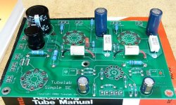
I got my Auricaps coupling caps but have a question. The caps are not labled with a +/-. From the board, C11 and C21 show a longer leg on the silk screen. I assumed that this was the positive side (like the longer leg of the radial legged caps). From the attached pictue, both caps have oppisite wire coloring to each other. Can I assume that if I install the caps where the lettering is upside down to the board that the polarity will be correct?
I will post some pictues of my hardware later sometime today.
Thanks,
skipper
Ok, so I will fuse the hot side, i've read some post that 2.5A slo-blow fuse is correct for the simple se? Does it matter if from the fuse, the hot goes to the blk/grn or the blk/white-grn/wht.
120 Volt Primary: Connect the two primary windings in parrallel.
Black adn Green connected together
Black/White and Green/White connected together
I got my Auricaps coupling caps but have a question. The caps are not labled with a +/-. From the board, C11 and C21 show a longer leg on the silk screen. I assumed that this was the positive side (like the longer leg of the radial legged caps). From the attached pictue, both caps have oppisite wire coloring to each other. Can I assume that if I install the caps where the lettering is upside down to the board that the polarity will be correct?
I will post some pictues of my hardware later sometime today.
Thanks,
skipper
Attachments
Re: can someone compare their wiring
All film/foil caps have no polarity, so you can connect them either way. If you visualize that the cap is built like a jelly-roll (it's a strip of mylar and a strip of foil laid on top of each other and rolled up), one lead is connected to the foil on the OD (outside dia) and the other lead is connected to the foil on the ID (inside dia). Some folks like to wire the foil OD side to the input (I think) for sonic reasons but I cannot notice any difference either way. They'll work just fine in either polarity.
If you buy boutique caps from Michael Percy, he puts a dot on the foil side before shipping them out. I typically wire them with the text facing the same direction for both caps (or all 4 for a PP amp), that way the foil ODs are all connected the same way (hopefully). That assumes that the text on the caps is always put on in the same orientation. I can just visualize caps shooting out of the cap-making machine into a big hopper and then going to the printing station in the factory.
On the transformer primary, wire as you have outlined above and connect the fused mains hot to either pair. The black/green pair would be my choice only because the other wires are both somewhat white to signify neutral, but connecting to either end will work.
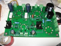
Here are a couple of pictures of my board. I still have to add the coupling caps. I plan on running it on a test bench. The inputs and spreaker jacks, where should I run the ground to these for the bench test? Do I just run them to the ground on the power connector?
Also, I got the currently limiters from mouser, so these should come off the fuse and to the power transformer?
Thanks,
Skipper
Also, I got the currently limiters from mouser, so these should come off the fuse and to the power transformer?
Thanks,
Skipper
Attachments
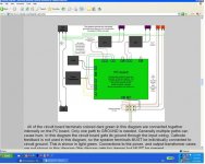
Put one on the primary side and put another in series with the center tap of the high voltage winding. The first one will heat up right away as the heaters come up due to their large current draw. The second is there to limit current when the rectifier comes up to temp. It takes a long time for the 5AR4 to come up, but once it starts it comes up fast. Those big caps draw a lot of current even before the rectifier is up to full temp and that's hard on the tube.
I do hope these transformers sound nice as the reviews on this forum.
From looking at the schematic, I see that the high voltage CT grounds the two high voltage legs. I bought two current limiter just in case I needed and extra so I will add it to the CT.
Another question, tonight I completed all the soldering on the board. I double checked the resistors as a sanity check. Everything checked out except R2 150K 3W and R4 150K 2W. The both seem to measure in the M Ohms and the values change,, they are not stable. I even put clips on the resistors to get a good reading. Is there a reason these are reading funning (.421 M ohm ) or are they just bad?
Skipper
Hey guys,
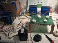
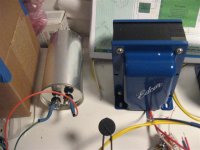
I am almost done with wiring up my bench top set up. I still have to connect up the OPT and add the tubes and I think I am done.
Should I ground the OPT and the PWRT cover to the inlet power conector ground (center pin) for the bench test?
Anything I should check before powering up? I added a current limiter to the high power CT and to the out let of the 2.5A slo-blo fuse.
Here are a couple of pictures of what I have so far.
Thanks,
skipper
skipper said:Should I ground the OPT and the PWRT cover to the inlet power conector ground (center pin) for the bench test?
I generally put a clip lead on each transformer/choke to earth ground, just in case. Don't forget to ground the OPT commons if they aren't already going back to the PCB for CFB as well as earth grounding some point on the PCB (George's instructions cover this).
Good luck!
Well I think I finally have it all wired up on the test bench. I had a lot of trouble trying to push in the 12AT7 tube into the socket. It seemed like either the pins where going to break or the board. I could not get the tube to sit flush on the socket.
I put it in snug but when I turned the amp on for the first time all the tubes lite up except the 12AT7 and I did not get any sound
So, any suggestion on seating the tube without breaking it. Are the pins easy to break or should I just try to force it on? This is a pretty small tube with little gold pins.
Thanks,
Skipper
Hey Guys,
Well I managed to push in the tube a little futher in and it is lighting up. It still does not sit flush but it is lighting up.
Still no sound. I am running in the basic triode mode with the speaker jacks being connected to the OPT directly.
I am using my Ipod as my input. I double checked everything before powering up. All the OP tubes are pretty bright. I am pretty sure I have the OPT wired correctly.
Any suggestion of where to start looking?
thanks,
skipper
Pushing a 9-pin tube into a brand-new socket can be pretty tight the first time....especially for PCB mount sockets. It's handy to have a few dead tubes around for jobs like this. The pins are pretty tough, but stress can compromise the seal between the pins and the glass. Are you sure that you didn't get any solder into the socket?
sailWickedFast said:Just ordered a Simple SE board for my first tube amp project. Looks like a great first ampHaven't touched a soldering iron in years, but after seeing this stuff, I'm hooked
Never realized DIY was so well established wow...
Welcome Sailwicked: There is tons of info here for the Tubelab simple SE, including support from Tubelab George himself if you have questions.
With a username like yours I figured your location had to be Boston or somewhere in New England. Hopefully, George will get you your board wicked fast
I don't think I got solder in the pins. If I look straight down into the socket, some holes look open while some look like there is some metal in there actually push against the pin. Unfortunately I do not have another old tube to work the socket in and out a few times. I actually have used quite a bit of force trying to get the tube in.
The tube seems to be lite, shouldn't I get some kind of sound out?
Thanks,
skipper
The tube seems to be lite, shouldn't I get some kind of sound out?
Thanks,
skipper
- Status
- This old topic is closed. If you want to reopen this topic, contact a moderator using the "Report Post" button.
- Home
- More Vendors...
- Tubelab
- simple se build