You probably won't though because you "don't really care"Don't know what the monster cables are made from or how they're made and I don't really care, will probably be tossing them in the bin. Might end up taking some pics before I do though.

It can make a significant change to the sub-100Hz FR of the speakers. I would not recommend it for passive speakers, but for actives it seems a valid tuning method. Rod Elliot uses it. But I don't want to open the currentdrive can of worms on here
Active is a completely different game. In a previous live I did some calculations
on the artificial change of the TS parameters after Stal (with a little circle above the a,
I cannot create that on my keyboard). That involved negative amplifier output
impedance to compensate the ohmic resistance of the coil. I gave up when I noticed
that the ohmic resistance is a moving target that changes MUCH depending on the
history of applied power.
That was in 8080 technology times. With current DSP processing one could
measure that in real time and try it again.
PS
And a 8 Ohm voice coil has usually +/- 4 Ohm resistance. Compare that
to a somewhat decent cable.
Last edited:
PS
And a 8 Ohm voice coil has usually +/- 4 Ohm resistance. Compare that
to a somewhat decent cable.
The vc resistance is the real part of the drivers impedance while the i part is the frequency variable part.
Why should I count that resistance twice?
Does it matter if the current drawn from the mains varies with the signal?
In reality it is pretty hard to avoid it, but I really have not measured what exactly the interaction is yet. If I can get my hands on some reasonable equipment, I would probably try.
Does it matter if the current drawn from the mains varies with the signal?
Only is the power supply is sh*te and can't provide a constant output...
Like many of these things, if it's affecting the sound it's bad design, as has often been stated here...
So, what is a "competent PSU ?.Sufficiently good isolation will be provided by any competent PSU.
Power cable sensitivity ?....what is such "poor electronic design" ?.As I often say, cable sensitivity is a sign of poor electronic design.
The final power cord from the source power (wall socket/power strip) will have variable LCR values (and other parasitic values) according to materials and construction....it is to be expected that these values will interact with the primary circuit, and through reflection the secondary circuit and according to reactivity/damping of both these two circuits.Of course, with a Class B or Class D amplifier the mains current draw will vary with the music envelope but no amount of fancy cables will change that.
Any non ideal cable will vary the instantaneous voltage, current and phase values according to changing current demand for a non resistive load.
All these reactive load parameters will set up excitations that may pass audibly through to the speakers.
Dan.
Monster Cable was one of my earlier venture into the cable changing game. For interconnects, they advertised the skin effects at various frequencies and used litz wire of three gauges to tackle the problem. Now that I think of it, you only need one single gauge and single conductor since the gauge would limit the maximum skin depth anyway while the current load is very low.
This makes sense to me, any limitation on current would most likely be a fault of the power supply, there are plenty of amps in the wall socket for any domestic amplifierOnly is the power supply is sh*te and can't provide a constant output...
Like many of these things, if it's affecting the sound it's bad design, as has often been stated here...
If you just consider the transformer, the rectifier, and the filtering caps, I wonder what other design options you have?
You seem to be a part swapper. There are also inductors and resistors and various ways to build various linear or shunt regulators.
There are also ways to build really good filters without capacitors.
Starting with a transformer there are different impedances and DC resistances of the windings to consider. You can choose to use full wave or bridge rectification. You can use choke input or capacitor input filters, heck even an inductor on the transformer primary works!
When we are beyond the grade school level actual design can happen and interaction of the chosen transformer values with the chosen diodes can be optimized. Then we can look at the time constants of the filter stages and check what our dominant poles are. Check the power supply impedance against frequency. And it goes on and on.
So much about "just ... the transformer, the rectifier, and the filtering caps"

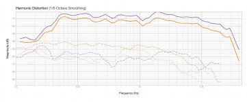
Good point. Here are the harmonic distortion plots. What is "CSD"?Have you looked at the CSD and distortion as well?
Attachments
Last edited:
I found listening to DC signals only negated all cable differences...
Especially 12Vdc sounds exciting.
It shouldn't matter with a guitar, but it's a different matter if the drums are reverse plugged, it can have a very unsettling effect....So if a guitarist plugs his cable in the wrong way around during recording, when you listen to it will you need to reverse the direction of your speaker cables?
It shouldn't matter with a guitar...
Even with palm-muted chugging? It can sound rather percussive.
So active, SS-driven with thick&short cables is for me. Others seem to hear things differently though.
You too are a fan of twisting 12 ga romex?
- Status
- Not open for further replies.
- Home
- Member Areas
- The Lounge
- Funniest snake oil theories