Are you referring to the TEK 109????
They were sooooo neat.. 250 picosecond 100 volt transitions into 50 ohms
jn
Yes, lost mine in a lab "clean-up" along with my Shibasoku 725.
I have a friend who has been dabbling with manufacturing cables, I doubt he is going to make his fortune from this...
I was at his place one day when he changed a set of interconnect cables for another which were visually identical. For want of a better expression one set sounded a little soft and fuzzy compared to the other. As it happens the more direct sounding pair had the RCA plugs laser welded by a local manufacturing jeweller. The other pair were soldered; identical cables and plugs.
I was simultaneously impressed and depressed that two connections per channel could be so audible.
This was just my observation and the test was sighted, though I didn't know what I was hearing until afterwards.
The cites more than 90 words ago about the Wiki article.
I meant cites about oxyidation speeded up by running 150uA through a wire.
I don't recall the manual mentioning shipping orientation nor operational orientation. Sounds reasonable though.
The biggest problem I had was the scopes of the day. It was necessary to use a very dark room and allow time for the eyes to adjust to the dark. Scopes of that time also had triggering issues, what a PITA.
jn
My worst give away ever was a 1963 Lumitron sampling scope. One of the greatest tour de forces of discrete design I ever saw. Used every exotic available, tunnel and snap diodes, gold doped transistors, etc. The sampling head was a GR connected hard line with a diode bridge soldered to the center conductor via holes drilled in the outer conductor and the hold capacitor was the grid capacitance of 6CW4's. The trigger circuit was a tunnel diode one shot that hit the sampler via a snap diode edge enhancer. It had a 25psec/div range in 1963.
Barrie Gilbert is the only person I know that knows the story, it came with a reed/charged line pulse generator predating the 109.
And they called Einstein crazy because he said light propagation was a speed limit ...Wow - solder your speaker leads & line leads both ends ?
You're crazier than me")
, Simple to test - just do it, and see if it makes a difference. I went the fully Monty 30 years ago, and never looked back. Courage, grasshopper ...
f.o. darkening -
Ahhh the chance to tell another short story -- I was supposed to be in charge of this new construction of a fiber optics lab.... once apon a time... It seems that x-rays given off during an underground n*****r device test darkens the f.o. data cable and thus attenuates the signal to the above ground signal capturing systems. We needed to calibrate the attenuation or we would never know what the actual signal strength/shape was.... and if possible find a cure for the darkening/attenuation. Hopefully, develop a new f.o. material for that harsh environment. Well, it seems that the French government had spent a fortune designing a scope which -with a hand held probe- could measure waveforms at frequencies in the light spectrum. I got the physicist number and called .... they only made two for their weapons R&D program and no more left to sell to USA. Well our physicist talked to theirs and some money passed hands and Bingo! ... months later we had a newly made light measuring scope in the new F.O. lab. Some great stuff never sees the light of day.
Thx-RNMarsh
PS - I have a TEK 7S12 with gen and sampling heads (S-52 and S6) that I don't know what to do with. <25ps. Who needs it?
Last edited:
Most of this craziness disappears when the full path has sufficient integrity - allow a weak spot to remain, and the characteristics of that are magnified by all the changes elsewhere. As an example, get some exotic cables which have audible differences - hardwire them and they then become largely indistinguishable ...I was simultaneously impressed and depressed that two connections per channel could be so audible.
This was just my observation and the test was sighted, though I didn't know what I was hearing until afterwards.
If I can find the mercury relays in my stash I'll try that test. How much current?
RE Wirewrap: I must have missed part of the discussion. RCA connectors can be quite marginal. I don't see how the latest fashion with a single point of contact improves the situation, especially wrt: shielding.
10 mA was enough for me to see changes.
The RCA was a follow up on another thread. I had mentioned 1.5 volts dc into a 10K load for an overnighter changed the performance of and RCA cable. That seems to have crossed to this thread. Scott rather than trying the numbers seems to have problems with the issue that there were changes in the connector contact quality. I thought that the actual small contact area with the length of time even though at a low current was obvious. So it is possible for passing dc through your interconnects does change the sound. But I don't think it is due to any of the manure quoted by the advocates of such practices.
My phono cart has only the contact point of the grid tube socket pin between it and active amplification; Otherwise it is all hard soldrerd. I have had a fire storm of critisim on two forums for doing this. Tim, of EAR fame, was the latest flame thrower. I'm never going back, for this was not a trivial increase in depth.Wow - solder your speaker leads & line leads both ends ?
You're crazier than me
Last edited:
I was at his place one day when he changed a set of interconnect cables for another which were visually identical. For want of a better expression one set sounded a little soft and fuzzy compared to the other. As it happens the more direct sounding pair had the RCA plugs laser welded by a local manufacturing jeweller. The other pair were soldered; identical cables and plugs.
I was simultaneously impressed and depressed that two connections per channel could be so audible.
I would be very interested to know your friends exact soldering technique and what brand of phono ( RCA ) plugs he used for this test. What kind of plating on the plugs. Did he clean / scrape / file the wires & plugs before soldering and if so exactly what method before we declare that even soldering is a floored connection method.
I have an unsubstantiated idea that filing down to bare, unplated metal seconds before soldering might be the most ideal method of connection using solder.
Another possible variable is whether he made a good mechanical hard metal to hard metal connection before he applied the solder. i.e. is the solder a third element in the signal path or just a way of covering and protecting a good mechanical joint.
I wonder if you enquired about these possible variables.
mike
One of the most significant benefits. Improved contacts reduces the level of subtle distortion imparted to finer signal variations, the notorious "micro detail", allowing the ear/brain to decipher more easily ambience cues in the recording, and relate them to the main musical content. This translates in the brain to greater apparent 'depth' to the sound scape, you start to hear things happening way back, well behind the main musical goings on.I'm never going back, for this was not a trivial increase in depth.
BTW have you seen Jim Williams article on mercury wetted relay switched potentials to measure settling time of 18bit DAC's? Tek sold these in the 60's as pulse generators, 1ppm in 265nS. AN120-1
“A part-per-million is a part-per-million. It’s magic. It’s the brass ring. It’s the holy grail of every measurement artist. It will mesmerize you, it will goad you, it will drive you crazy and, if you’re lucky, it will reward you. A part-per-million is a part-per-million.”
Jerrold R. Zacharias
M.I.T. physicist, mentoring a young, very naïve investigator.
Page 30 and on:
http://cds.linear.com/docs/en/application-note/an120f.pdf
Joachim and Scott
My
 was for the acoustic effects on the resistive loading (they confirm my own conclusion).
As for the height of the simulated peaks I concur with the comments of Scott and yours. They are too high.
Why? The simulation is correct as far as the electrical part of the chain is concerned. (*)
The deviation from the reality is to be found on the lacking sim model of the cartridge. There, we have to model the mechanical part of the cartridge and then we have to model the coupling of the mechanical part with the electrical part of the cartridge.
The mechanical part model will give some HF resonances which are in the sub 100kHz range. (**)
The mechanical to electrical part coupling is to be modelled by a transformer. The coupling coefficient M is disappointing and I am afraid is frequency dependent too. (***)
The HF energy in the vinyl music grooves doesn’t go too high in frequency.
The system exciter is surface scratches and needle mistracking. These can excite the mechanical part.
The resonances of the moving mechanical parts will be attenuated by the coupling coefficient M and will be electrically LP filtered by the L of the coil. So don’t expect much HF signal-related excitation energy at the cartridge pins/interconnect cable interface.
George
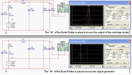
(*) Joachim, please ask Mr. Carr about the pick-up point for these simulations. See on the attachment below how the effects change when the Bode Plotter input point changes (all else equal).
(**) http://shure.custhelp.com/ci/fattach/get/29245/
(***) I have not managed to excite HF mechanical resonance when I was feeding the coils with my signal generator (up to 2MHz). This with a DL-103 and various MM cartridges.
Attachments
Last edited:
And they called Einstein crazy because he said light propagation was a speed limit ...
Simple to test - just do it, and see if it makes a difference. I went the fully Monty 30 years ago, and never looked back. Courage, grasshopper ...
Actually I have been there before and will probably go there again but perhaps not while I'm still developing the system - just too inconvenient.
. . . but I am avoiding sending the signal through the shaft of a speaker binding post and then through a plug rather I just have the incoming & outgoing wires crushed together in the binding post - for now that's good enough - but thx for the reminder
Forgive me for sounding stupid, but how can a few mechanical joints in the home cause so much trouble to a signal which has already passed through quite a few joints in the recording studio or the concert hall? Or do top recording engineers now weld all their cables into fixed configurations? Must make it fun to get them on and off the van when doing on-site recording!
Part of the answer is that recording studios are dealing with low level signals during recording, the power levels in the electronics and power supplies at this time are relatively low, and constant. The typical erratic power consumption in class AB power stages seems to bring out the worst in this type of distortion artifact.
Another part of the answer is that many recordings do suffer from all kinds of deficiencies.
I have heard that some recording studios convert the signals to digital close to the mics thus eliminating that particular set of problems.
Surely we all have noticed that some recording are much better than others ? ?
I have heard that some recording studios convert the signals to digital close to the mics thus eliminating that particular set of problems.
Surely we all have noticed that some recording are much better than others ? ?
What has power consumption got to do with signal integrity at a mechanical joint?
Aldi's user manual likely suggests to solder the power cord direct to the mains socket. (and the case should be bolted+welded to the nearest main house-ground point)
- Status
- Not open for further replies.
- Home
- Member Areas
- The Lounge
- John Curl's Blowtorch preamplifier part II