JN
I have had a chance to think about the last set of measurements and the Scott,
Don't pull the rope! It is not a snake or a tree or even a wall. Don't pull the rope. As usual I think we both have quite different perspectives on the National IC test results. When I presented what I thought was a simple circuit to write the equation virtually no one could do it. So below is attached the schematic of how I perceive their test setup. You are welcome to try the circuit equations or to model it. I suspect my back of envelope calculations are certainly within an order of magnitude or much closer than the factor of 100 you feel is right. (I can do the equations for a "Noise Amplifier" circuit as shown. The basic issues are not what is the noise gain (I think we agree it is 100) but what is the signal gain and input impedance. I have set the input source to model the AP System 2. I think this will help clear the air about the differences we get, (I think we are starting with different assumptions.)
The signal gain is one and since the 10 Ohm resistor is bootstrapped by the Aol of the op-amp (divided by the feedback factor), the input resistance is very large, any bench generator has no trouble driving this +-10V. ALL errors refered to the op-amp input noise, CMRR, distortion, etc. have a gain of 101 to the output. Do you really not see that? Simply consider a nearly ideal op-amp put 10V on the + input the op-amp forces the - input and the output to 10V by feedback i.e. there is no current in either resistor, the circuit acts like a gain of 1 follower, and the input resistance is very large. If need be say the op-amp has an Aol of 10^6 so 10uV appears across the 10 Ohm this is all the generator needs to supply i.e. the input looks like 1Meg Ohm.
It would take 5 min to drop this into a plug board and see what this circuit does, we have used it for 40yr. The 10 Ohm and 1k Ohm have no effect on the noise or distortion (except at the third or fouth decimal place). If you want take an op-amp that is only -90dB thirds (so we can eliminate subtleties) you will see -50dB thirds at the output. jcx is right the distortion is not separable from common mode effects limiting its usefulness.
BTW those app notes you guys are throwing around have some circuits that have nothing to do with this one.
Last edited:
My pot is bigger than your:
eBay | GROS POTENTIOMETRE BOBINE DOUBLE 2x4,7K 4W 1000V MCB
eBay | GROS POTENTIOMETRE BOBINE DOUBLE 2x4,7K 4W 1000V MCB
Today all I wanted was a big serving of avgolemeno, so I made my own..
Avgolemono ! For some fat, tasty soup, a pie or for roast dressing ? Try a bit of oregano or thymus in it.
Our local Greek community has seemed to dissapear
It started from there! Dick was prophetic.
BTW those app notes you guys are throwing around have some circuits that have nothing to do with this one.
The battering was from me.
Although four url links didn’t consume a lot of site’s bandwidth, I’ll explain:
The two Nat Sem Appl. Notes were posted because they showed the successive progression towards the ultra low distortion test fixture for the LM4562 , starting from typical laboratory apparatus and at the same time explaining the methodology and the merits.
The article of Michael Renardson doesn’t need defending. It is really good and useful overall if one has time to read it.
The Xavier Ramus article caters for people not having APs to their possession.
The problem is that the recent twist started from distortion, went to HD+N and I see it ending in noise. All very low level and exactly because of this, difficult to extract and differentiate between these two with analogue instrumentation. DSP methods, successful in telecommunications, could be used here.
George
Correct. I use something similar with noise gain 80dB and signal gain 1 to reveal opamp imperfections.
Pavel
How do you achieve this 80/1 ?
Using the op amp as an active filter which at some frequencies has low signal gain but it’s noise gain remains the same?
George
Using an added switch to get 2X24 steps ?My device of choice for adjusting levels is a switched attenuator. 24 position devices can be obtained from a number of vendors.
Pavel
How do you achieve this 80/1 ?
Using the op amp as an active filter which at some frequencies has low signal gain but it’s noise gain remains the same?
George
Similarly as in Scott's link (Ed's image). 80dB is a noise gain and 0dB (= gain +1) is a signal gain. Try OP177 datasheet, Figure 26, e.g.
This is all ----. Of course anybody can make an attenuator out of almost anything, including some old TV or instrument chassis for Pots. That is not what we are talking about here, QUALITY is the key.
And what makes quality? Good engineering and GOOD PARTS.
It is a shame that so many of you out there live so far away from my location. I have armloads of parts that I would love to dump on you eager attenuator makers, just to make room for the GOOD PARTS. You may not thank me in the end though, because once you made your 'attenuator' and it just sort of works OK, you may realize you could have gone to the equivalent of RADIO SHACK and gotten something more accurate, quiet, and lower distortion, especially over time, and not wasted your initial effort in the first place, even if the parts were free.
Quality requires care and selection in the switches and resistors. Far more care than most of you address today. Better to stick with the simple and store bought, for most of you.
Again, John, "quality" means nothing, it is just marketing blah blah.
How do-you define-it ? Price ? Look ? Reputation ? Proved long lasting ?
Why an OPA with non measurable distortion, <2nv/sqHz, 50ma of drive capability, hight slew rate etc... is not Quality ?
An electrochemical cap can be defined by its ESR, temperature, etc. That, i understand, but quality ?
How do-you define-it ? Price ? Look ? Reputation ? Proved long lasting ?
Why an OPA with non measurable distortion, <2nv/sqHz, 50ma of drive capability, hight slew rate etc... is not Quality ?
An electrochemical cap can be defined by its ESR, temperature, etc. That, i understand, but quality ?
Last edited:
Better to stick with the simple and store bought, for most of you.
We unwashed masses are too busy staring at the ground and drooling.
Again, John, "quality" means nothing, it is just marketing blah blah.
How do-you define-it ?...
John did define quality in the post you were answering to. Do you read
your own posts only ? Is your only goal to make comments like the one
you just did ? Probably quality means nothing to you, but for others it does.
Similarly as in Scott's link (Ed's image). 80dB is a noise gain and 0dB (= gain +1) is a signal gain. Try OP177 datasheet, Figure 26, e.g.
Careful PMA this is the inverting version of distortion amplification, it does not rely on synthetic input resistance. The non-inverting version is related to gyrators, SRPP, etc. and I don't think think yet that Ed see's that the test circuit is no load on the generator i.e. the generator impedance does not matter at all and to the first order there is no signal current in either resistor.
Careful PMA this is the inverting version of distortion amplification, it does not rely on synthetic input resistance. The non-inverting version is related to gyrators, SRPP, etc. and I don't think think yet that Ed see's that the test circuit is no load on the generator i.e. the generator impedance does not matter at all and to the first order there is no signal current in either resistor.
Scott,
I don't think you got my reference to the parable of the blind men and the elephant. Each looked at parts and thought they had the whole.
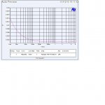
Making standard measurements of the AP is mostly autopilot. If you don't pay attention to the details you get very pretty graphs of nonsense.
Attached is a THD curve that shows the noise limit and the maximum voltage out of the unit. (It gave me an error message when I tried higher source voltages.)
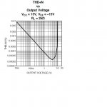
The second attachment is the best curve of the LM4562 as there is a gain of about 100 be sure to reduce the label values.
I showed you the current source version of the test circuit as shown in the data sheet. Now from prior questions it seems almost no one here can even write the loop equations, which I thought were obvious from inspection.
Trying to get the same view of the Elephant how do you read the limit of the AP trying to display what is shown?
ES
PS I see I forgot to do log on the voltage so the graphs don't look the same!
Attachments
Last edited:
I remember those caps we used to build our amps in 70, bought near a French manufacturer . It was their 'top quality' line.
It is only 20 years after that it was sure they were pure junk, all dry.
That is the sens of my question. I believe audio parts are engineering, defined by their characteristics, on catalog then measurements, not vine or fashion.
About pots, my question was not so insane: what can-we measure to ensure a pot is a "quality" parts. Of course, i got no answer.
If you dislike my comments, please, just add me in your ignore list, as i do for you right now, for the same reason and with my best regards.
It is only 20 years after that it was sure they were pure junk, all dry.
That is the sens of my question. I believe audio parts are engineering, defined by their characteristics, on catalog then measurements, not vine or fashion.
About pots, my question was not so insane: what can-we measure to ensure a pot is a "quality" parts. Of course, i got no answer.
No, or we don't have the same definition of "define". It is like "Right part".John did define quality in the post you were answering to. .
If you dislike my comments, please, just add me in your ignore list, as i do for you right now, for the same reason and with my best regards.
Things change, I guess.
How so? They all found good use.
- Status
- Not open for further replies.
- Home
- Member Areas
- The Lounge
- John Curl's Blowtorch preamplifier part II